

Description
DW-54/30 Nitrogen Compressor – Ultra-High-Pressure Oil-Free N2 Booster for 3.00 MPa Demanding Process Applications
Engineered to deliver 50 m³/min at 3.00 MPa discharge pressure, the DW-54/30 is a two-stage, four-row oil-free piston nitrogen compressor designed for the most demanding high-pressure industrial gas applications. Four-stage compression, massive flow capacity, and zero oil contamination for critical petrochemical, gas liquefaction, and pipeline injection operations.
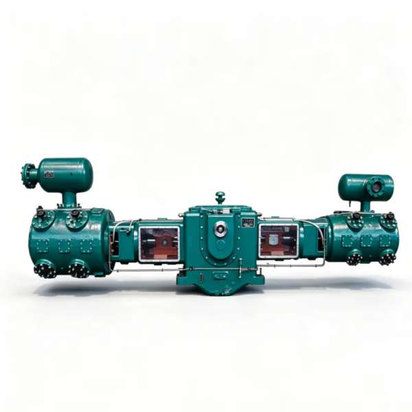
Product Overview
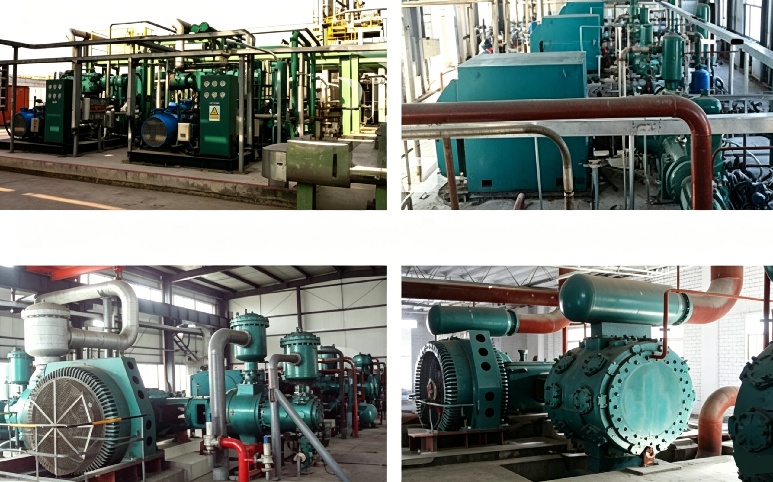
The DW-54/30 nitrogen compressor stands at the apex of our oil-free piston compressor portfolio, representing the culmination of advanced engineering for ultra-high-pressure industrial gas applications. With a formidable capacity of 50 m³/min and an exceptional 3.00 MPa discharge pressure, this unit addresses the most demanding nitrogen compression requirements found in large-scale petrochemical operations, gas liquefaction plants, and high-pressure pipeline injection systems.
What distinguishes the DW-54/30 from all other models in our lineup is its four-stage, two-row (二列四级) compression architecture. This multi-stage design is absolutely essential for achieving the 3.00 MPa discharge pressure while maintaining thermodynamic efficiency and preserving the integrity of the oil-free PTFE sealing system. Each of the four compression stages is equipped with an independent intercooler, creating a cascade of progressively higher pressure cylinders that divide the enormous overall pressure ratio into manageable segments. Without this staged approach, the discharge temperatures would exceed the safe operating limits of oil-free sealing materials, making four-stage compression a fundamental engineering requirement rather than an optional feature.
The compressor maintains our commitment to fully oil-free compression through advanced PTFE composite piston rings and rider bands that operate without hydrocarbon lubricants. At 3.00 MPa, the risk of oil contamination is magnified exponentially compared to low-pressure applications, as any oil vapor present would be concentrated to dangerous levels. The DW-54/30’s native oil-free design achieves ISO 8573-1 Class 0 certification without any downstream purification equipment, making it the only viable choice for ultra-high-pressure applications where nitrogen purity is non-negotiable.
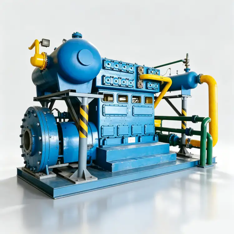
Technical Specifications – DW-54/30
| Parameter | Value | Unit |
|---|---|---|
| Model | DW-54/30 | – |
| Pattern | Two-stage, Four-row (二列四级) | – |
| Capacity | 50 | m³/min |
| Discharge Pressure | 3.00 | MPa |
| Compressor Size (L × W × H) | 5456 × 3518 × 2535 | mm |
| Weight | 13.00 | t |
| Power | 630 | kW |
| Voltage | 6k or 10k | V |
| Gas Medium | Nitrogen (N₂) | – |
| Lubrication | Oil-free | – |
* All specifications are rated at standard reference conditions (ISO 1217, Annex C). Actual performance may vary based on site altitude, ambient temperature, and inlet conditions.
Key Features & Engineering Advantages
1. Four-Stage Compression for Ultra-High Pressure
The DW-54/30 employs a four-stage, two-row compression architecture that is unique within our product portfolio and essential for achieving 3.00 MPa discharge pressure. The overall pressure ratio of approximately 30:1 to 60:1 (depending on inlet conditions) is divided across four sequentially arranged compression cylinders, with inter-stage cooling after each stage. This cascade approach limits the pressure ratio per stage to approximately 2.5:1 to 3.5:1, keeping discharge temperatures below 160°C and preserving the dimensional stability of the PTFE sealing elements. Without four-stage compression, the discharge temperature would exceed 250°C, far beyond the safe limit of oil-free materials. Each stage features progressively smaller cylinder bores to accommodate the reduced gas volume at higher pressures, optimizing volumetric efficiency across the entire pressure range.
2. High-Pressure Oil-Free PTFE Sealing System
The DW-54/30 utilizes an advanced self-lubricating piston ring and rider band system manufactured from ultra-high-performance PTFE composites specifically formulated for 3.00 MPa service. These rings are reinforced with high-aspect-ratio glass fibers, bronze particulates, and proprietary additives that enhance creep resistance and dimensional stability under extreme pressure. The material achieves a coefficient of friction below 0.05 without any hydrocarbon lubrication, ensuring the nitrogen stream remains completely free of oil contamination. At 3.00 MPa, even trace oil contamination would be concentrated to levels that would render the nitrogen unusable for most industrial applications, making the oil-free design an absolute requirement rather than a preference.
3. Heavy-Duty Reinforced Frame for Extreme Mechanical Loads
The main frame is cast from GG30 gray cast iron (equivalent to ASTM A48 Class 35B) with substantially reinforced wall sections, additional ribbing, and integral cooling water passages. The four-cylinder arrangement generates significant peak gas forces at 3.00 MPa, requiring frame stiffness far exceeding that of lower-pressure models. The two-row opposed-cylinder layout provides partial force cancellation, but the sheer magnitude of the gas loads at ultra-high pressure necessitates a foundation mass of minimum 20 tonnes to ensure stable operation. The crankshaft is forged from 34CrNiMo6 alloy steel (higher grade than standard 42CrMo4) and undergoes precision grinding and dynamic balancing to ISO 1940 G1.0 standards to minimize vibration at the high operating loads.
4. Medium-Voltage Motor Drive for High-Power Operation
The DW-54/30 is driven by a 630 kW medium-voltage induction motor available in either 6kV or 10kV configurations, conforming to IEC 60034-1 efficiency class IE3. At 630 kW, low-voltage 380V operation would require impractical cable sizes and switchgear ratings, making medium-voltage drive mandatory. The motor is directly coupled to the compressor crankshaft through a heavy-duty flexible disc coupling rated for the torque and misalignment requirements of high-pressure reciprocating service. Direct medium-voltage integration reduces electrical losses, minimizes cable infrastructure, and ensures compatibility with standard industrial power distribution in large process plants.
Application Scenarios
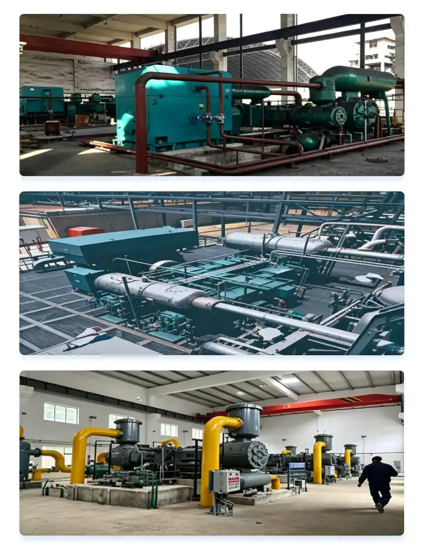
Ultra-High-Pressure Pipeline Nitrogen Injection
In long-distance nitrogen pipeline systems and high-pressure gas distribution networks, the DW-54/30 serves as the primary high-pressure booster station. Its 3.00 MPa discharge pressure is sufficient to overcome pipeline friction losses over distances exceeding 50 km and to maintain adequate pressure at the most remote consumers. The 50 m³/min capacity can supply multiple high-pressure tapping points simultaneously, making it suitable for centralized nitrogen supply to large industrial complexes. The oil-free design is critical in pipeline applications because any contamination would propagate throughout the entire distribution network, affecting all downstream consumers.
Gas Liquefaction Plant High-Pressure Booster
In nitrogen liquefaction facilities, the DW-54/30 nitrogen booster compresses nitrogen from the liquefier cold end or storage vaporizer to the high pressure required for liquefaction cycle efficiency. The 3.00 MPa discharge pressure is typical for Claude-cycle liquefiers and other high-pressure nitrogen liquefaction processes where elevated pressure is essential for achieving cryogenic temperatures through expansion. The massive 50 m³/min capacity matches the throughput of medium-to-large-scale liquefaction plants producing 50–100 tons per day of liquid nitrogen. The oil-free design prevents contamination of the liquefier heat exchangers, which would severely degrade thermal performance and require costly defrosting and cleaning.
Petrochemical Emergency Nitrogen Injection & Purging
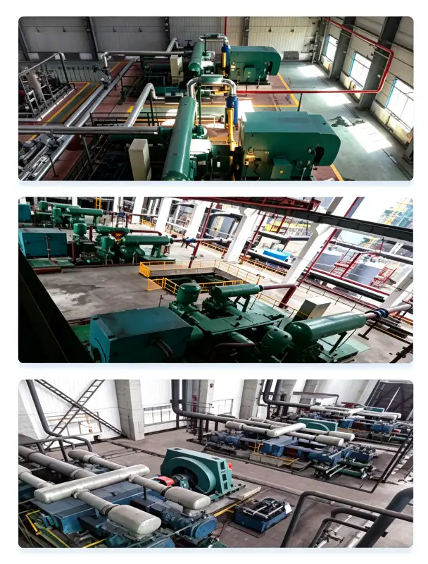
In petrochemical and refinery operations, the DW-54/30 provides ultra-high-pressure nitrogen for emergency reactor inerting, catalyst bed preservation, high-pressure vessel purging, and safety system nitrogen supply. The 3.00 MPa discharge pressure is sufficient to inject nitrogen into virtually any process vessel or reactor system, including those operating at elevated pressures. The continuous-duty rating ensures that emergency nitrogen is available instantaneously without the warm-up delays associated with starting standby compressors. The oil-free certification is mandatory for petrochemical applications where nitrogen contacts catalyst beds, enters process streams, or is used for product-quality-sensitive operations.
Underground Gas Storage & Cavern Sealing
Underground gas storage facilities, including salt caverns and depleted reservoirs, require high-pressure nitrogen for cushion gas injection, cavern sealing, and pressure maintenance during gas withdrawal cycles. The DW-54/30’s 3.00 MPa discharge pressure is adequate for injecting nitrogen into storage caverns operating at pressures up to 2.50 MPa, maintaining the structural integrity of the cavern walls and preventing groundwater ingress. The 50 m³/min capacity allows rapid filling of large storage volumes, reducing the time required for cavern commissioning and maintenance operations. The oil-free design prevents contamination of the stored gas, which is critical when the stored nitrogen is later withdrawn for high-purity applications.
Material & Construction
The DW-54/30 is constructed from premium materials selected for ultra-high-pressure nitrogen compatibility, extreme mechanical loading, and extended operational life:
| Component | Material | Specification |
|---|---|---|
| Frame | Gray Cast Iron | GG30 / HT300, heavily reinforced with ribbing |
| Crankshaft | Forged Alloy Steel | 34CrNiMo6, Q&T, ISO 1940 G1.0 balanced |
| Cylinder Blocks (All Stages) | Gray Cast Iron | GG30 / HT300, progressive wall thickening for HP stages |
| Piston Rings | PTFE-Glass-Bronze Composite | Ultra-high-pressure rated, 185°C max, creep-resistant |
| Rider Bands | PTFE Composite | High-load guidance, anti-scuffing, wear rate <0.03 mm/1000h |
| Valve Plates | Stainless Steel | SS316, heavy-duty concentric ring spring design |
| Intercoolers (1–3) | Carbon Steel Shell / SS316 Tubes | ASME VIII Div.1, 1.5× hydrotest, 30 min hold |
| Aftercooler | Carbon Steel Shell / SS316 Tubes | High-pressure finned tube, 32°C cooling water |
| High-Pressure Piping | Seamless Stainless Steel | SS316, ANSI Class 900 flanges, 100% RT |
| Base Frame | Heavy Structural Steel | Welded box-section, vibration-damped mounting |
All pressure-bearing components are designed and fabricated in strict accordance with ASME BPVC Section VIII Division 1 or Chinese GB 150 standards. Every weld joint undergoes 100% radiographic inspection (RT) per ASME Section V, Article 2, and each completed pressure vessel is subjected to a hydrostatic pressure test at 1.5 times the maximum allowable working pressure (MAWP) for a minimum hold period of 30 minutes. High-pressure piping systems are fabricated from seamless SS316 with ANSI Class 900 flanged connections to ensure leak-tight integrity at 3.00 MPa operating pressure.
Installation & Maintenance Guidelines
Foundation & Structural Requirements
The DW-54/30 has a dry weight of 13.00 tonnes and a center of gravity approximately 1,000 mm above the baseplate. The four-cylinder arrangement generates substantial peak gas forces at 3.00 MPa, requiring a reinforced concrete inertia block of minimum 20 tonnes. The block must be mounted on heavy-duty elastomeric vibration isolators (natural frequency 5–7 Hz) or spring isolators to prevent vibration transmission to adjacent structures. The foundation must be designed by a qualified structural engineer to support the dynamic loads, which include both the reciprocating inertia forces and the gas pressure pulsations. Minimum clearance requirements: 2.0 m on the non-drive side for valve access, 1.5 m on the drive side for motor maintenance, and 2.5 m overhead for crane access during major overhauls.
Cooling Water System Design
Cooling water demand is approximately 80 m³/h at an inlet temperature not exceeding 32°C. The water distribution circuit supplies the cylinder jackets and three intercoolers in parallel branches, with the aftercooler on a separate circuit. Given the four-stage compression and high pressure ratio, the intercoolers are absolutely critical for thermal management and must receive priority cooling water flow. Water quality specifications: pH 6.5–8.5, total dissolved solids < 400 mg/L, chloride content < 30 mg/L (to prevent SS316 tube corrosion in the high-pressure coolers), suspended solids < 20 mg/L, and total hardness < 250 mg/L as CaCO₃. A closed-loop cooling tower with side-stream filtration and automated chemical treatment is mandatory for reliable operation.
Preventive Maintenance Schedule
| Interval | Service Item | Action Required |
|---|---|---|
| Daily | Operational Inspection | Check vibration, abnormal noise, cooling water flow, all stage pressures and temperatures |
| 200 hours | Valve Plate Inspection (HP stages) | Inspect 3rd and 4th stage valves for carbon deposits, spring fatigue, cracking |
| 500 hours | Valve Plate Inspection (All stages) | Inspect all stage valves, replace any showing wear or leakage |
| 1,000 hours | Piston Ring Wear Assessment | Measure ring groove clearance on all stages; replace if > 0.18 mm |
| 3,000 hours | Intermediate Overhaul | Replace all piston rings, rider bands, and valve plate assemblies across all stages |
| 6,000 hours | Major Overhaul | Inspect crankshaft journals, measure all bearing clearances, replace main bearings if >0.06 mm |
The oil-free design of the DW-54/30 eliminates the extensive maintenance requirements of lubricated alternatives. There are no oil changes, no oil analysis, no filter replacements, and no separator cartridge changes. The primary consumable wear items are the PTFE piston rings and rider bands, which typically achieve 3,000–5,000 hours of service life under clean nitrogen conditions. However, the high-pressure valve plates (particularly stages 3 and 4) may require more frequent inspection due to the extreme mechanical stress at 3.00 MPa. The four-stage design actually extends the life of individual components by reducing the stress per stage compared to a two-stage design operating at the same overall pressure ratio.

Compliance & Safety Certifications
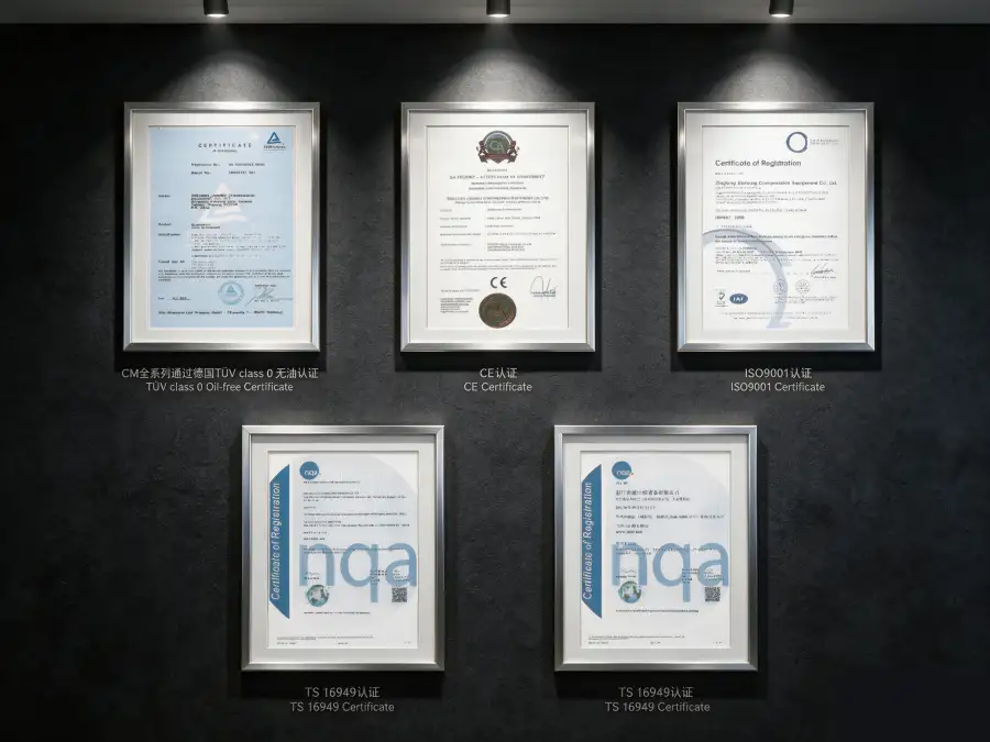
The DW-54/30 nitrogen compressor is designed, manufactured, and tested to meet or exceed the following international standards and regulatory frameworks:
ASME BPVC Section VIII Div.1, GB 150-2011, PED 2014/68/EU Module A
IEC 60034-1 (IE3 efficiency), IEC 60204-1, ISO 12100 machinery safety
ISO 8573-1 Class 0 (Oil Content), independently tested by TÜV Rheinland
ISO 9001:2015, ISO 14001:2015
Nitrogen is classified as a simple asphyxiant gas. At 3.00 MPa discharge pressure, the risk of catastrophic gas release and rapid oxygen displacement is extremely high. All DW-54/30 installations must incorporate: (1) Continuous oxygen deficiency monitoring with multiple sensors in the compressor room; (2) High-pressure discharge piping with pressure relief valves rated at 110% of MAWP and rupture discs as secondary protection; (3) Automatic isolation valves on suction and discharge that close on emergency shutdown; (4) Ventilation systems maintaining ambient oxygen above 19.5% per OSHA 29 CFR 1910.146; (5) Emergency shutdown interlocks at 19.5% O₂ (alarm) and 18.0% O₂ (hard shutdown); (6) Personnel trained in ultra-high-pressure gas safety protocols; (7) Restricted access to the compressor area with authorized-entry procedures. All high-pressure piping must be designed, fabricated, and inspected by qualified pressure piping specialists.
Performance & Efficiency Analysis
The DW-54/30 achieves a specific power consumption of approximately 12.60 kW per m³/min of nitrogen delivered at 3.00 MPa discharge pressure. This specific power figure reflects the thermodynamic reality of ultra-high-pressure compression, where the work required increases dramatically with pressure ratio. However, the four-stage design with inter-stage cooling maintains this figure within a competitive range for oil-free compressors in the ultra-high-pressure segment. For comparison, oil-lubricated reciprocating compressors in similar applications typically consume 13.5–15.0 kW/m³/min, while diaphragm compressors (often selected for oil-free ultra-high-pressure service) may exceed 18 kW/m³/min and deliver only a fraction of the capacity.
Over an 8,000-hour annual operating schedule, the DW-54/30’s four-stage efficiency advantage versus less efficient alternatives yields approximately 360,000–720,000 kWh of annual energy savings. At $0.08/kWh, this represents $28,800–$57,600 in direct electricity cost reduction per year. However, the primary economic justification for the DW-54/30 is typically the elimination of oil-related consumables and the avoidance of downstream purification equipment that would be mandatory with lubricated alternatives. The total cost of ownership for ultra-high-pressure nitrogen compression is reduced by an estimated 25–35% over a 10-year operational life when oil-free operation is compared to lubricated systems with full downstream purification.
At 3.00 MPa, the concentration effect of oil contamination is severe. A lubricated compressor producing nitrogen with 1.0 mg/m³ oil content at atmospheric pressure would deliver nitrogen with approximately 30 mg/m³ oil content at 3.00 MPa due to the compression and condensation effects. This level of contamination would be catastrophic for virtually all industrial applications, making the DW-54/30’s native oil-free design not merely preferable but absolutely essential for ultra-high-pressure service.
Customization & OEM Capabilities
We offer comprehensive customization options to adapt the DW-54/30 to specific site conditions, integration requirements, and end-user specifications:
- Skid-Mounted Turnkey Packages: The compressor, motor, all four intercoolers, aftercooler, high-pressure discharge piping, instrumentation, and control panel are pre-assembled on a heavy-duty structural steel skid with integrated lifting lugs and anchor bolt templates. Factory pre-testing of all systems reduces commissioning time and risk.
- Hazardous Area Configurations: ATEX Zone 2 and IECEx compliant motor and electrical enclosures for petrochemical installations. Integrated gas detection, automatic ventilation interlocks, and explosion-proof instrumentation can be incorporated into the control system.
- Advanced Process Control: Siemens S7-1500 or Allen-Bradley ControlLogix PLC with 15-inch HMI touchscreen, remote monitoring via Modbus TCP/IP or OPC-UA, and seamless DCS/SCADA integration. Automatic stage sequencing, load/unload control, and variable frequency drive (VFD) compatibility optimize efficiency and reduce mechanical wear.
- Environmental Protection: C5-M marine-grade coating systems for coastal installations; tropicalized electrical components for 55°C ambient; and IP54-rated acoustic enclosures with special high-pressure noise attenuation reducing emission from 88 dB(A) to 75 dB(A) at 1 meter.
- OEM & Private Label: Custom paint colors, branded nameplates, and localized documentation packages for gas equipment distributors and system integrators serving global markets.
Custom configurations are available from MOQ 1 unit. Engineering review and proposal generation typically require 7–10 business days due to the complexity of the four-stage system. Standard delivery time is 16–20 weeks; repeat orders are delivered in 12–14 weeks from order confirmation.
Case Study: LNG Plant Nitrogen Liquefaction Booster
Client: A mid-scale LNG liquefaction facility in Malaysia producing 500,000 tons per year
Challenge: The facility’s nitrogen liquefaction unit was using two oil-lubricated compressors in series to achieve the 2.80 MPa required for the Claude-cycle liquefier. The oil contamination from the compressors was progressively fouling the liquefier’s aluminum plate-fin heat exchangers, reducing thermal efficiency by 15% over 18 months and requiring expensive defrosting and cleaning cycles every 6 months. The two-compressor arrangement also had poor reliability, with unplanned outages causing LNG production losses of $50,000 per day.
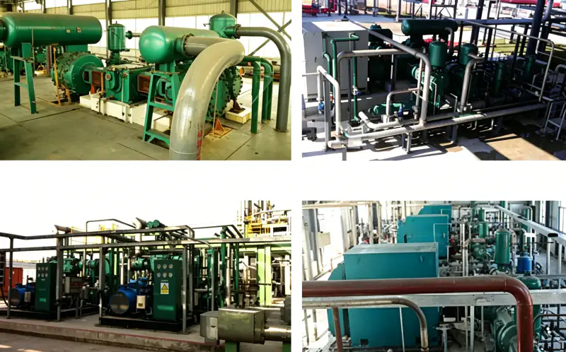
Solution: We supplied a DW-54/30 oil-free nitrogen compressor as a single-unit replacement for the two existing compressors, configured on a custom skid with all four intercoolers, aftercooler, and a Siemens S7-1500 PLC control panel with full SCADA integration. The 3.00 MPa discharge pressure exceeded the liquefier’s requirement, providing a pressure margin that improved cycle efficiency. The oil-free design eliminated heat exchanger fouling entirely. A 10 m³ surge vessel was installed upstream to buffer demand fluctuations from the liquefier.
Quantified Results After 36 Months:
- Heat exchanger fouling: Eliminated completely, restoring thermal efficiency to design levels
- Defrosting cycles: Eliminated, saving $120,000/year in maintenance and production downtime
- Unplanned outages: Zero events in 36 months versus 8 events with the previous two-compressor system
- LNG production losses avoided: $400,000 over 36 months
- Energy consumption: Improved by 8.2% versus the replaced system, saving $32,000/year
- Payback period: 2.5 years including avoided production losses and maintenance savings
“The DW-54/30 has been the single most impactful equipment upgrade in our plant’s history. The elimination of oil contamination has restored our liquefier performance, and the reliability improvement has been remarkable. We haven’t had a single unplanned outage in three years.” — Chief Operating Officer, LNG Facility
FAQ & Selection Guide
Related Products & Solutions
DW-36/30 High-Pressure Nitrogen Compressor
A smaller-capacity four-stage oil-free compressor delivering 36 m³/min at 3.00 MPa. Ideal for applications where the full 50 m³/min of the DW-54/30 is not required, offering lower capital cost and reduced foundation requirements.
ZW Series Multi-Stage Oil-Free Compressors
Vertical, multi-stage oil-free compressors for oxygen, nitrogen, hydrogen, and specialty gases. Discharge pressures up to 9.00 MPa for ultra-high-pressure gas filling and specialized chemical process applications.
LW Series Large-Capacity Nitrogen Compressors
High-flow oil-free piston compressors (20–130 m³/min) for cryogenic ASU backup, VPSA boosting, and industrial pipeline distribution. Discharge pressures from 0.30 to 0.80 MPa for medium-pressure applications.
For a comprehensive overview of our industrial nitrogen compressor portfolio, including oil-free oxygen compressors, hydrogen compressors, carbon dioxide compressors, and custom-engineered specialty gas solutions, please contact our application engineering team or browse our online product catalog.
Ready to Deploy Ultra-High-Pressure Nitrogen Compression?
Our senior application engineers are available to evaluate your ultra-high-pressure nitrogen requirements, including flow demands, suction conditions, discharge pressure targets, foundation constraints, and integration with existing process systems. We provide comprehensive technical proposals, foundation design guidance, piping and instrumentation diagrams (P&IDs), and detailed total cost of ownership (TCO) analyses within 5–7 business days of receiving your inquiry.
Email: [email protected] | Response within 24 hours

























