
Beschrijving
4MW-80/30 stikstofcompressor – ultra-krachtige viertraps olievrije N2-booster voor industriële processen van 3,00 MPa
De 4MW-80/30 is een viertraps, vierrijige olievrije zuigercompressor voor stikstof, ontworpen om een debiet van 80 m³/min te leveren bij een persdruk van 3,00 MPa. Hij is bedoeld voor de meest veeleisende grootschalige industriële toepassingen. Geen olieverontreiniging, een enorm debiet en geoptimaliseerd voor continu bedrijf bij verhoogde druk in petrochemische, staal- en gasverwerkingsinstallaties.
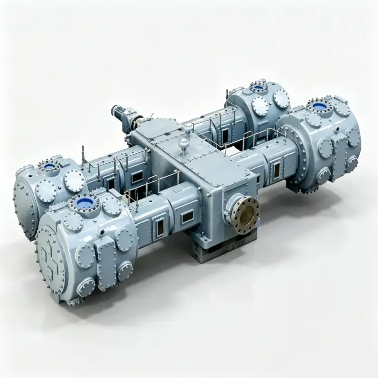
Productoverzicht
De 4MW-80/30 stikstofcompressor Dit vertegenwoordigt het hoogtepunt van onze engineering op het gebied van olievrije zuigercompressoren, ontworpen voor de meest veeleisende grootschalige industriële toepassingen waar tegelijkertijd een enorme doorvoercapaciteit en een verhoogde persdruk vereist zijn. Met een indrukwekkende Capaciteit van 80 m³/min en een 3,00 MPa uitlaatdrukDeze unit bevindt zich in het ultra-high-performance segment van ons portfolio industriële stikstofcompressoren en wordt gebruikt door de grootste cryogene luchtseparatie-installaties, geïntegreerde staalfabrieken en petrochemische complexen.
Wat de 4MW-80/30 onderscheidt van alle andere modellen in ons assortiment is zijn viertraps, vier rijen (四列四级) Compressiearchitectuur. Dit meertrapsontwerp is essentieel voor het beheersen van de extreme drukverhouding die nodig is om een persdruk van 3,00 MPa te bereiken, terwijl de thermische stabiliteit behouden blijft en de integriteit van de olievrije PTFE-afdichtingselementen gewaarborgd blijft. Elke trap is uitgerust met een onafhankelijke tussenkoeler, waardoor de gastemperaturen binnen veilige bedrijfsgrenzen blijven, zelfs bij langdurig gebruik op maximale capaciteit. Het massieve gietijzeren frame en de zware, gesmede stalen krukas zijn ontworpen voor een minimale levensduur van 120.000 uur onder strenge industriële omstandigheden.
De compressor behoudt ons kenmerkende ontwerp. volledig olievrij compressiepad Door gebruik te maken van zelfsmurende PTFE-composiet zuigerveren en geleidebanden. Bij een persdruk van 3,00 MPa is het risico op oliedampoverdracht exponentieel hoger dan bij toepassingen met lage druk, waardoor het olievrije ontwerp niet alleen voordelig, maar absoluut noodzakelijk is. De 4MW-80/30 bereikt dit. native ISO 8573-1 Klasse 0-certificering Zonder dat er stroomafwaarts oliefiltratieapparatuur nodig is, wordt gegarandeerd dat de stikstofzuiverheid voldoet aan de strengste eisen voor toepassingen in de voedingsmiddelenindustrie, farmaceutische productie, halfgeleiderfabricage en petrochemische processen.
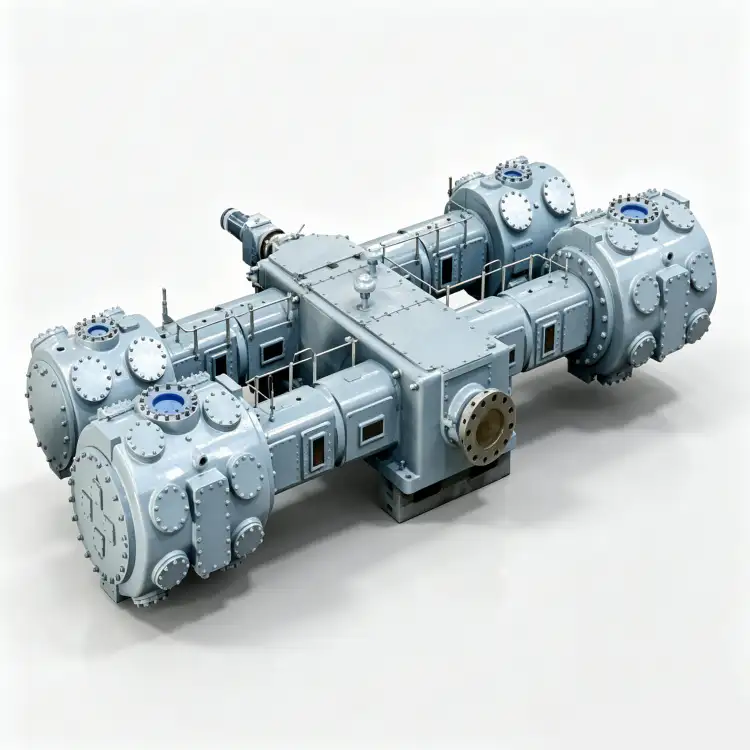
Technische specificaties – 4MW-80/30
| Parameter | Waarde | Eenheid |
|---|---|---|
| Model | 4MW-80/30 | – |
| Patroon | Viertraps, vier rijen (四列四级) | – |
| Capaciteit | 80 | m³/min |
| Afvoerdruk | 3.00 | MPa |
| Compressorafmetingen (L × B × H) | 6800 × 4000 × 3200 | mm |
| Gewicht | 26.00 | T |
| Stroom | 900 | kW |
| Spanning | 6k of 10k | V |
| Gasmedium | Stikstof (N₂) | – |
| Smering | Olievrij | – |
* Alle specificaties zijn gebaseerd op standaard referentieomstandigheden (ISO 1217, bijlage C). De werkelijke prestaties kunnen variëren afhankelijk van de hoogte van de locatie, de omgevingstemperatuur en de inlaatcondities.
Belangrijkste kenmerken en technische voordelen
1. Viertrapscompressie voor extreme drukverhoudingen
De architectuur in vier fasen en vier rijen (四列四级). De compressieverhouding van de 4MW-80/30 is een fundamentele technische vereiste om een persdruk van 3,00 MPa te bereiken bij typische inlaatcondities van 0,05–0,10 MPa. De totale drukverhouding van circa 30:1 tot 60:1 wordt verdeeld over vier compressiecilinders, waarbij elke trap werkt met een beheersbare drukverhouding van 2,5:1 tot 3,5:1. Tussen elke trap voert een speciale, zeer efficiënte buizenwarmtewisselaar de compressiewarmte af, waardoor de perstemperatuur onder de 150 °C blijft en thermische degradatie van de PTFE-afdichtingselementen wordt voorkomen. Zonder deze gefaseerde aanpak zou de perstemperatuur boven de 250 °C uitkomen, ver boven de veilige bedrijfslimiet van olievrije materialen. De vierrijige opstelling zorgt bovendien voor een superieure krachtbalans, waarbij de traagheidskrachten van de eerste en tweede orde elkaar grotendeels opheffen tussen de tegenover elkaar liggende cilinderparen.
2. Hoogwaardig olievrij PTFE-afdichtingssysteem
De 4MW-80/30 maakt gebruik van een gepatenteerde technologie. zelfsmurende zuigerveer- en geleidebandassemblage Vervaardigd uit ultrahoogwaardige PTFE-composieten, specifiek samengesteld voor meertraps hogedruktoepassingen. Deze ringen zijn versterkt met glasvezel, bronsdeeltjes en molybdeendisulfide om een wrijvingscoëfficiënt van minder dan 0,05 te bereiken zonder externe koolwaterstofsmering. Bij een persdruk van 3,00 MPa zou de partiële druk van eventuele oliedamp ongeveer 30 keer hoger zijn dan bij 0,30 MPa, waardoor olieverontreiniging stroomafwaarts vrijwel onmogelijk te verwijderen is. Het van nature olievrije ontwerp van de 4MW-80/30 bereikt dit. ISO 8573-1 Klasse 0-certificering Zonder verdere filtratie, adsorptie of monitoringapparatuur. De PTFE-formulering is geschikt voor continu gebruik bij temperaturen tot 185 °C en is bestand tegen de cumulatieve thermische belasting van vier compressiestappen.
3. Massief, zwaar frame met geavanceerde krachtbalans.
Het hoofdframe is gegoten uit GG30 grijs gietijzer (gelijkwaardig aan ASTM A48 Klasse 35B) met versterkte wandsecties tot 80 mm dik en geïntegreerde koelwaterkanalen die direct in het gietstuk zijn gefreesd. vierrijige opstelling van tegenover elkaar geplaatste cilinders Dit zorgt voor een uitzonderlijke krachtbalans, waarbij traagheidskrachten van de eerste orde elkaar opheffen tussen aangrenzende cilinderparen en krachten van de tweede orde worden geminimaliseerd door de symmetrische fasering van de krukas. Deze geavanceerde mechanische balans reduceert de onbalanskrachten die op de fundering worden overgebracht met meer dan 901 TP3T in vergelijking met ontwerpen met één rij cilinders, ondanks de enorme capaciteit van 80 m³/min. Het gewicht van 26,00 ton en de lengte van 6,8 meter weerspiegelen de industriële schaal van deze machine, die is ontworpen voor installatie in speciale compressorhuizen met een stevige fundering en toegang voor een bovenloopkraan.
4. Krachtige middenspanningsaandrijving voor industriële integratie
De 4MW-80/30 wordt aangedreven door een 900 kW middenspanningsinductiemotor Verkrijgbaar in 6kV- of 10kV-uitvoeringen, conform IEC 60034-1 efficiëntieklasse IE3. Bij dit vermogensniveau is middenspanningsaandrijving noodzakelijk voor een praktische elektriciteitsdistributie; de motorstroom bij 380V zou meer dan 1600 ampère bedragen, wat onpraktische kabeldiameters en schakelapparatuur vereist. De 6kV- of 10kV-uitvoering maakt directe integratie in industriële middenspanningsdistributienetwerken mogelijk met motorstromen van 100-170 ampère, waardoor standaard kabeldiameters en conventionele schakelapparatuur mogelijk zijn. De motor is voorzien van een vloeistofkoelingsmantel voor gebruik in tropische klimaten en heeft isolatieklasse F met temperatuurstijgingsklasse B voor een ruimere thermische marge.
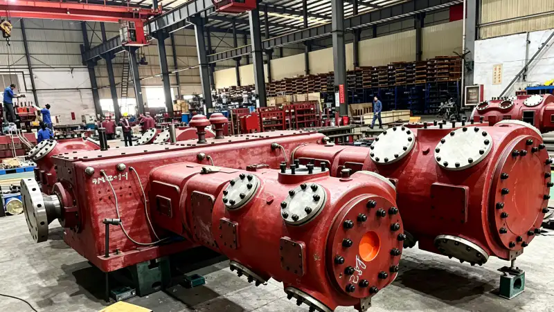
Toepassingsscenario's
Ultra-grootschalige cryogene luchtseparatie-installaties
In 's werelds grootste cryogene ASU-installaties die 5.000–15.000 Nm³/u gasvormige stikstof produceren, dient de 4MW-80/30 als de primaire hogedruk stikstofbooster Tussen de koelbox en het distributienetwerk. De capaciteit van 80 m³/min komt overeen met de output van de grootste luchtseparatie-units (ASU's) met één installatie, terwijl de persdruk van 3,00 MPa voldoende druk levert voor distributie via pijpleidingen over lange afstanden naar afnemers in uitgestrekte industriële complexen. Het olievrije ontwerp is absoluut cruciaal in deze toepassingen, omdat het stikstofdistributienetwerk meerdere afnemers bedient met uiteenlopende zuiverheidseisen, van inertisering in staalfabrieken (tolerant voor kleine onzuiverheden) tot de halfgeleiderindustrie (vereiste verontreinigingsniveaus van minder dan ppb). Elke olieverontreiniging bij de booster zou zich door het hele distributiesysteem verspreiden en alle afnemers treffen.
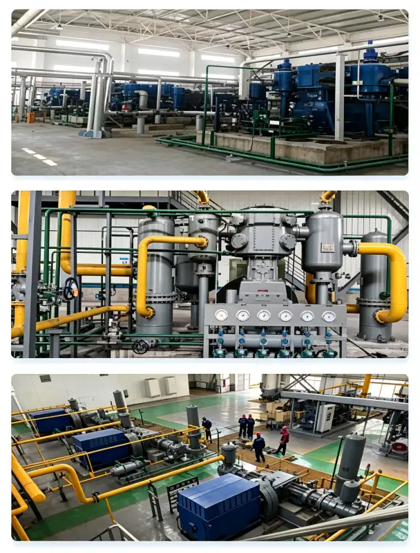
Geïntegreerde hogedruk-stikstofsystemen voor staalfabrieken
Moderne, geïntegreerde staalfabrieken met meerdere hoogovens, basiszuurstofovens en continu-gietlijnen vereisen enorme hoeveelheden stikstof onder hoge druk Voor het inertiseren van verdeelbakken, de metallurgie van de gietpan, het afdichten van hoogovengas en het spoelen van vaten in noodsituaties. De capaciteit van 80 m³/min van de 4MW-80/30 maakt het mogelijk om gelijktijdig meerdere staalproductie-eenheden te bedienen via een gecentraliseerde stikstofleiding met een druk van 3,00 MPa. De verhoogde persdruk is essentieel om de tegendruk van moderne verdeelbaksystemen (werkend bij 1,5–2,0 MPa) te overwinnen en een positieve afdichtingsgasstroom bij de hoogoventuyères te handhaven. 4MW-80/30 hogedruk stikstofcompressor Het systeem wordt ingezet in staalfabrieken in heel Azië, waar de betrouwbaarheid en olievrije werking cruciaal zijn gebleken voor het behoud van de gietkwaliteit en het verminderen van verstoppingen in de verdeelbak.
Petrochemische hogedrukproces- en noodsystemen
In petrochemische complexen en raffinaderijen levert de 4MW-80/30 stikstof onder hoge druk voor Behoud van reactorkatalysatoren, inertisering van hydrocrackers, noodinjectie van stikstof in hogedrukvaten en druktesten van pijpleidingenDe persdruk van 3,00 MPa is voldoende om stikstof in vrijwel alle procesvaten en reactorsystemen te injecteren, waardoor een positieve inerte gaslaag behouden blijft tijdens opstarten, uitschakelen en noodsituaties. De classificatie voor continu bedrijf garandeert een ononderbroken beschikbaarheid van stikstof tijdens langdurige onderhoudsbeurten. De olievrije certificering is verplicht voor petrochemische toepassingen waarbij stikstof in contact komt met katalysatorbedden of in processtromen terechtkomt die volledig koolwaterstofvrij moeten blijven om katalysatorvergiftiging of productverontreiniging te voorkomen.
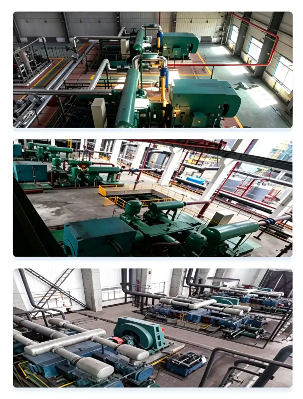
Gasvloeistof- en pijpleidingboosterstations
Grootschalige stikstofvloeibaarmakingsinstallaties en gastransportleidingnetwerken vereisen compressoren met een hoge capaciteit en hoge druk om stikstof over lange afstanden en door cryogene verwerkingsapparatuur te transporteren. De combinatie van een debiet van 80 m³/min en een druk van 3,00 MPa maakt de 4MW-80/30 ideaal voor pijpleidingpompstations die de stroom en druk handhaven over honderden kilometers aan distributieleidingen. In vloeibaarmakingsinstallaties pompt de compressor stikstof vanuit de verdamper van de vloeibaarmaker op tot de druk die nodig is voor opslag en distributie. Het olievrije ontwerp zorgt ervoor dat er geen verontreinigingen in het cryogene systeem terechtkomen, waar ze zouden kunnen bevriezen en warmtewisselaars blokkeren.
Materiaal en constructie
De 4MW-80/30 is vervaardigd uit hoogwaardige materialen die geselecteerd zijn op hun geschiktheid voor stikstof onder ultrahoge druk, hun thermische weerstand en hun enorme structurele integriteit.
| component | Materiaal | Specificatie |
|---|---|---|
| Hoofdframe | Grijs gietijzer | GG30 / HT300, 80 mm wanddikte, geïntegreerde koelkanalen |
| Cilinderblokken (alle fasen) | Grijs gietijzer | GG30 / HT300, progressieve wandverdikking voor hogere stadia |
| Krukas | Gesmeed gelegeerd staal | 42CrMo4, Q&T, ISO 1940 G2.5 dynamisch gebalanceerd, 6 slagen |
| Zuigerveren | PTFE-Glas-Brons-MoS₂-composiet | Geschikt voor extreem hoge druk, zelfsmorend, maximale temperatuur 185 °C |
| Rider Bands | PTFE-composiet | Zuigergeleiding, anti-slijtage, slijtagesnelheid <0,03 mm/1000 uur |
| Klepplaten | Roestvrij staal | SS316, concentrische hogedrukring met versterkte veren |
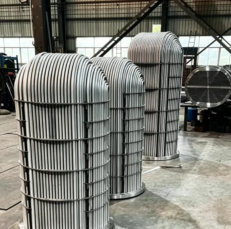
| Intercoolers (3 stuks) | Behuizing van koolstofstaal / buizen van RVS 316 | ASME VIII Div.1, 1,5× hydrotest, 30 min vasthouden per test |
| Nakoeler | Behuizing van koolstofstaal / buizen van RVS 316 | Hogedrukbuis met ribben, geschikt voor koelwater van 32°C |
| Hogedrukleidingen | Naadloos roestvrij staal | SS316, ANSI Klasse 900 flenzen voor een druk van 3,00 MPa. |
| Basisframe | Zwaar constructiestaal | Gelaste constructie, trillingsgedempte montage, hijsogen |
Alle drukdragende componenten worden ontworpen en vervaardigd in strikte overeenstemming met ASME BPVC Sectie VIII Divisie 1 of de Chinese GB 150-normen. Elke lasverbinding ondergaat een 100% röntgeninspectie (RT) volgens ASME Sectie V, Artikel 2, en elk voltooid drukvat wordt onderworpen aan een hydrostatische druktest bij 1,5 keer de maximaal toelaatbare werkdruk (MAWP) gedurende een minimale wachttijd van 30 minuten. Hogedrukleidingsystemen worden vervaardigd van naadloos SS316 met ANSI Klasse 900 flensverbindingen om lekdichtheid te garanderen bij een werkdruk van 3,00 MPa.
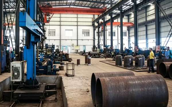
Installatie- en onderhoudsrichtlijnen
Fundament- en constructie-eisen
De 4MW-80/30 heeft een drooggewicht van 26,00 ton en een zwaartepunt op circa 1200 mm boven de grondplaat. Dankzij het ontwerp met vier rijen tegenover elkaar geplaatste cilinders worden onbalanskrachten ondanks de enorme capaciteit uitzonderlijk goed beheerst, waardoor installatie op een gewapend betonnen traagheidsblok van 40-50 tonHet blok moet worden gemonteerd op zware, elastomere trillingsdempers (eigen frequentie 4–6 Hz) om trillingsoverdracht naar aangrenzende constructies te voorkomen. Minimale vrije ruimte: 2,5 m aan de niet-aandrijfzijde voor toegang tot de kleppen, 2,0 m aan de aandrijfzijde voor motoronderhoud en 3,0 m boven de motor voor toegang met een kraan tijdens grote revisies. De fundering moet worden ontworpen door een gekwalificeerde constructeur en moet rekening houden met dynamische belastingen tijdens opstarten, uitschakelen en noodsituaties.
Ontwerp van koelwatersystemen
De koelwaterbehoefte bedraagt ongeveer 120 m³/h bij een inlaattemperatuur van maximaal 32 °C. Het waterdistributiecircuit voorziet de cilindermantels, drie tussenkoelers en de nakoeler van water via parallelle aftakkingen met individuele debietregelkleppen. Gezien de viertrapscompressie zijn de tussenkoelers cruciaal voor het thermisch beheer en moeten ze prioritaire koelwatertoevoer krijgen. Specificaties voor de waterkwaliteit: pH 6,5–8,5, totaal opgeloste stoffen < 500 mg/L, chloridegehalte < 50 mg/L (om corrosie van de SS316-buizen te voorkomen), zwevende deeltjes < 30 mg/L en totale hardheid < 300 mg/L als CaCO₃. Een speciaal gesloten koeltorensysteem met zijstroomfiltratie en automatische chemische behandeling is essentieel voor een betrouwbare werking.
Preventief onderhoudsschema
| Interval | Serviceartikel | Actie vereist |
|---|---|---|
| Dagelijks | Operationele inspectie | Controleer trillingen, abnormale geluiden, koelwaterdebiet, uitlaattemperaturen en -drukken van alle trappen. |
| 250 uur | Kleppenplaatinspectie (alle fasen) | Verwijder en inspecteer de zuig-/perskleppen op koolstofafzettingen, veermoeheid en scheuren. |
| 1.000 uur | Beoordeling van zuigerveerslijtage (alle fasen) | Meet de speling in de groef van de zuigerveren; vervang de zuigerveren als de speling groter is dan 0,20 mm. |
| 3.000 uur | Tussentijdse revisie | Vervang alle zuigerveren, geleidebanden en klepplaatassemblages in alle vier de fasen. |
| 6.000 uur | Grote revisie | Controleer de krukaslagertappen, meet alle lagerspelingen en vervang de hoofdlagers indien deze groter zijn dan 0,08 mm. |
Het olievrije ontwerp van de 4MW-80/30 vermindert de onderhoudscomplexiteit aanzienlijk in vergelijking met gesmeerde alternatieven met een vergelijkbare capaciteit. Er zijn geen olieverversingen nodig (waarvoor meer dan 500 liter per verversing nodig zou zijn), geen contracten met olieanalyselaboratoria, geen voorraad filterelementen en geen vervanging van separatorpatronen. De belangrijkste slijtageonderdelen zijn de PTFE-zuigerveren en geleidebandendie doorgaans een levensduur van 3.000 tot 5.000 bedrijfsuren halen onder schone stikstofomstandigheden. Het ontwerp met vier fasen verdeelt de slijtage gelijkmatiger over de machine, waardoor de piekbelasting op elk afzonderlijk onderdeel wordt verminderd.
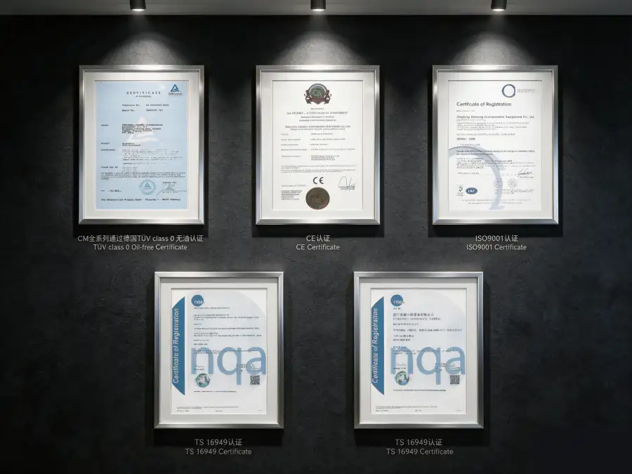
Certificeringen voor naleving en veiligheid
De 4MW-80/30 stikstofcompressor is ontworpen, gefabriceerd en getest om te voldoen aan, of te overtreffen, de volgende internationale normen en wettelijke kaders:
ASME BPVC Sectie VIII Div.1, GB 150-2011, PED 2014/68/EU Module A
IEC 60034-1 (IE3-efficiëntie), IEC 60204-1, ISO 12100 machineveiligheid
ISO 8573-1 Klasse 0 (oliegehalte), onafhankelijk getest door TÜV Rheinland
ISO 9001:2015, ISO 14001:2015
Stikstof wordt geclassificeerd als een eenvoudig verstikkend gas. Bij een persdruk van 3,00 MPa is het risico op een catastrofale gaslekkage en snelle zuurstofverdringing extreem groot. Alle 4MW-80/30-installaties moeten het volgende omvatten: (1) Continue bewaking van zuurstoftekort in het gehele compressorhuis en aangrenzende ruimten; (2) Hogedrukpersleidingen met overdrukventielen met een nominale druk van 1101 TP3T MAWP en breekplaten als secundaire beveiliging; (3) Noodafsluitkleppen op de zuig- en persleidingen met automatische sluiting bij gasdetectie of zuurstofalarm; (4) Ventilatiesystemen die zijn ontworpen om de omgevingszuurstof boven 19,51 TP3T te houden volgens OSHA 29 CFR 1910.146; (5) Noodstopvergrendelingen die activeren bij 19,51 TP3T O₂ (alarm) en een volledige uitschakeling veroorzaken bij 18,01 TP3T O₂; (6) Personeel dat is opgeleid in veiligheidsprotocollen voor ultrahogedrukgassen en beschikt over gecertificeerde ademhalingsapparatuur voor noodgevallen. Alle hogedrukleidingen moeten jaarlijks worden geïnspecteerd op corrosie, erosie en mechanische schade.
Prestatie- en efficiëntieanalyse
De 4MW-80/30 behaalt een specifiek energieverbruik van circa 11,25 kW per m³/min stikstof wordt geleverd bij een persdruk van 3,00 MPa. Dit specifieke vermogen weerspiegelt de thermodynamische realiteit van ultrahogedrukcompressie in vier trappen. Binnen het segment van olievrije zuigercompressoren met ultrahoge capaciteit (capaciteit >60 m³/min, druk >2,00 MPa) is dit rendement concurrerend en vaak zelfs superieur aan alternatieve technologieën. Ter vergelijking: oliegesmeerde zuigercompressoren in vergelijkbare toepassingen verbruiken doorgaans 12,0–14,0 kW/m³/min, terwijl pogingen om een gelijkwaardige prestatie te bereiken met meerdere schroefcompressoren in serie complexe koeling tussen de trappen zouden vereisen en nog steeds niet zouden voldoen aan de olievrije certificering.
Bij een standaard jaarlijks bedrijfsschema van 8.000 uur levert het efficiëntievoordeel van de 4MW-80/30 ten opzichte van minder efficiënte alternatieven een rendement op van ongeveer 480.000–960.000 kWh aan jaarlijkse energiebesparingBij een tarief van $0,08/kWh vertegenwoordigt dit een directe besparing op de elektriciteitskosten van $38.400–$76.800 per jaar. De belangrijkste economische drijfveer voor de keuze voor een 4MW-80/30-systeem is echter doorgaans de het elimineren van oliegerelateerde verbruiksartikelen en het vermijden van apparatuur voor olieverwijdering verderop in het proces. Dat zou verplicht zijn bij elk alternatief met smeermiddel. totale eigendomskosten voor ultra-hogedruk stikstofcompressie De uitstoot wordt naar schatting met 20–30% verminderd gedurende een operationele levensduur van 10 jaar wanneer de olievrije 4MW-80/30 wordt vergeleken met gesmeerde systemen met volledige nazuivering.
Het ontwerp met vier fasen biedt een extra efficiëntievoordeel doordat optimalisatie van de koeling tussen de trappenElke tussenkoeler is zo gedimensioneerd dat de temperatuur ervan de temperatuur van het koelwater tot op 5 °C nauwkeurig benadert. Dit maximaliseert de dichtheid van het gas dat de volgende trap ingaat en vermindert het volume gas dat gecomprimeerd moet worden. Deze gefaseerde koeling verbetert de algehele isotherme efficiëntie van het compressieproces met ongeveer 151 TP3T in vergelijking met adiabatische compressie zonder tussenkoeling.
Mogelijkheden voor maatwerk en OEM-productie
We bieden uitgebreide aanpassingsmogelijkheden om de 4MW-80/30 af te stemmen op specifieke locatieomstandigheden, integratievereisten en specificaties van de eindgebruiker:
- Kant-en-klare pakketinstallatie: De compressor, motor, alle vier de tussenkoelers, nakoeler, hogedrukleidingen, instrumentatie en besturingssystemen zijn voorgemonteerd op een massief stalen frame met geïntegreerde hijsbalken en ankerbouten. Door alle systemen vooraf in de fabriek te testen, wordt de inbedrijfstellingstijd verkort en worden de risico's op locatie geminimaliseerd.
- Configuraties van gevaarlijke zones: Motor- en elektrische behuizingen die voldoen aan de ATEX Zone 2- en IECEx-normen voor petrochemische installaties. Geïntegreerde gasdetectie, automatische ventilatie en nooduitschakelsystemen kunnen in de besturingsarchitectuur worden opgenomen.
- Geavanceerde procesbesturing: Siemens S7-1500 of Allen-Bradley ControlLogix PLC met 15-inch HMI-touchscreen, redundante bewaking op afstand via Modbus TCP/IP en OPC-UA, en naadloze DCS/SCADA-integratie. Automatische lastverdeling, compatibiliteit met frequentieomvormers (VFD's) en voorspellende onderhoudsalgoritmen optimaliseren de beschikbaarheid en verminderen ongeplande uitvaltijd.
- Milieubescherming: C5-M coatingsystemen van maritieme kwaliteit voor installaties aan de kust; tropische elektrische componenten voor omgevingstemperaturen tot 55 °C; en op maat gemaakte geluidsisolerende behuizingen die de geluidsemissie reduceren van 88 dB(A) tot 75 dB(A) op 1 meter afstand voor installaties in de buurt van bewoonde gebouwen.
- Reserveonderdelen en servicecontracten: Uitgebreide reserveonderdelenpakketten, inclusief essentiële slijtageonderdelen voor 2 jaar gebruik; door de fabriek opgeleide servicemonteurs beschikbaar voor inbedrijfstelling, onderhoud en noodhulp; en langetermijnserviceovereenkomsten met gegarandeerde beschikbaarheid.
Aangepaste configuraties zijn beschikbaar via Minimale bestelhoeveelheid: 1 stukGezien de omvang van de 4MW-80/30 duurt de technische beoordeling en het opstellen van een offerte doorgaans 10 tot 14 werkdagen. De standaard levertijd bedraagt 16 tot 20 weken; versnelde levering binnen 14 weken is mogelijk voor in aanmerking komende bestellingen met vastgestelde technische specificaties.
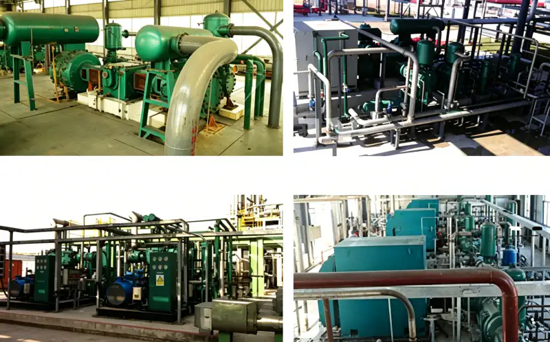
Casestudie: Geïntegreerde upgrade van het stikstofsysteem in een staalfabriek
Cliënt: Een belangrijke geïntegreerde staalproducent in Zuidoost-Azië met drie hoogovens, twee BOF-converters en zes continu-gietlijnen.
Uitdaging: De staalfabriek gebruikte drie oliegesmeerde compressoren (gezamenlijke capaciteit 75 m³/min, maximale druk 2,00 MPa) om stikstof aan de gehele fabriek te leveren. Het systeem draaide op volle capaciteit, zonder redundantie voor onderhoud of storingen. Olieverontreiniging veroorzaakte verstoppingen in de verdeelbakken bij 151 ton gietstukken, wat resulteerde in 1,4 ton gietstukken en 2,5 miljoen stuks per jaar aan kwaliteitsverlies en herstelwerkzaamheden. De druk van 2,00 MPa was onvoldoende voor de nieuwe hogedruktechnologie voor het inertiseren van de verdeelbakken die werd geïmplementeerd op de nieuwste gietlijn. De klant had behoefte aan één compressor die de verouderde installaties kon vervangen, redundantie kon bieden en een druk van 3,00 MPa kon leveren voor de nieuwe apparatuur.
Oplossing: Wij leverden een 4MW-80/30 olievrije stikstofcompressor Als primaire stikstoftoevoer werd de compressor geïnstalleerd op een kant-en-klaar frame met alle vier de tussenkoelers, de nakoeler, hogedrukleidingen en een Siemens S7-1500 PLC-besturingspaneel met volledige SCADA-integratie. De persdruk van 3,00 MPa voldeed aan de nieuwe eisen voor de verdeelbak en zorgde voor voldoende opvoerhoogte voor het gehele distributienetwerk van de fabriek. Het olievrije ontwerp voorkwam vervuiling van alle gietsystemen. Een van de bestaande compressoren werd behouden als noodreserve.
Gekwantificeerde resultaten na 30 maanden:
- Stikstofgehalte van de olie: Verlaagd van 3,8 mg/m³ naar <0,01 mg/m³, waarbij ISO 8573-1 Klasse 0 is behaald
- Verstopping van de sproeier in de verdeelgoot: Uitgeschakeldwaardoor de gietopbrengst verbeterde van 94,2% naar 97,8%
- Kwaliteitsverlies en herstelkosten: Verminderd met $2,1 miljoen/jaar
- Onderhoudskosten (drie oude compressoren versus één nieuwe): Verminderd met 38%
- Energieverbruik: Verbeterd met 8.5% versus de vervangen vloot, wat een besparing oplevert van $42.000/jaar
- Ongeplande downtime: Nul gebeurtenissen in 30 maanden; de oude compressoren hadden gemiddeld 12 dagen ongeplande stilstand per jaar.
“De 4MW-80/30 heeft onze stikstofvoorziening getransformeerd van een constante bron van problemen naar een betrouwbare voorziening waar we ons nooit zorgen over hoeven te maken. De eliminatie van olieverontreiniging heeft zichzelf ruimschoots terugverdiend door de verbeterde gietkwaliteit. We zijn nu van plan een tweede unit te installeren in onze andere fabriek.” — Vicepresident Operations, Geïntegreerde Staalproducent
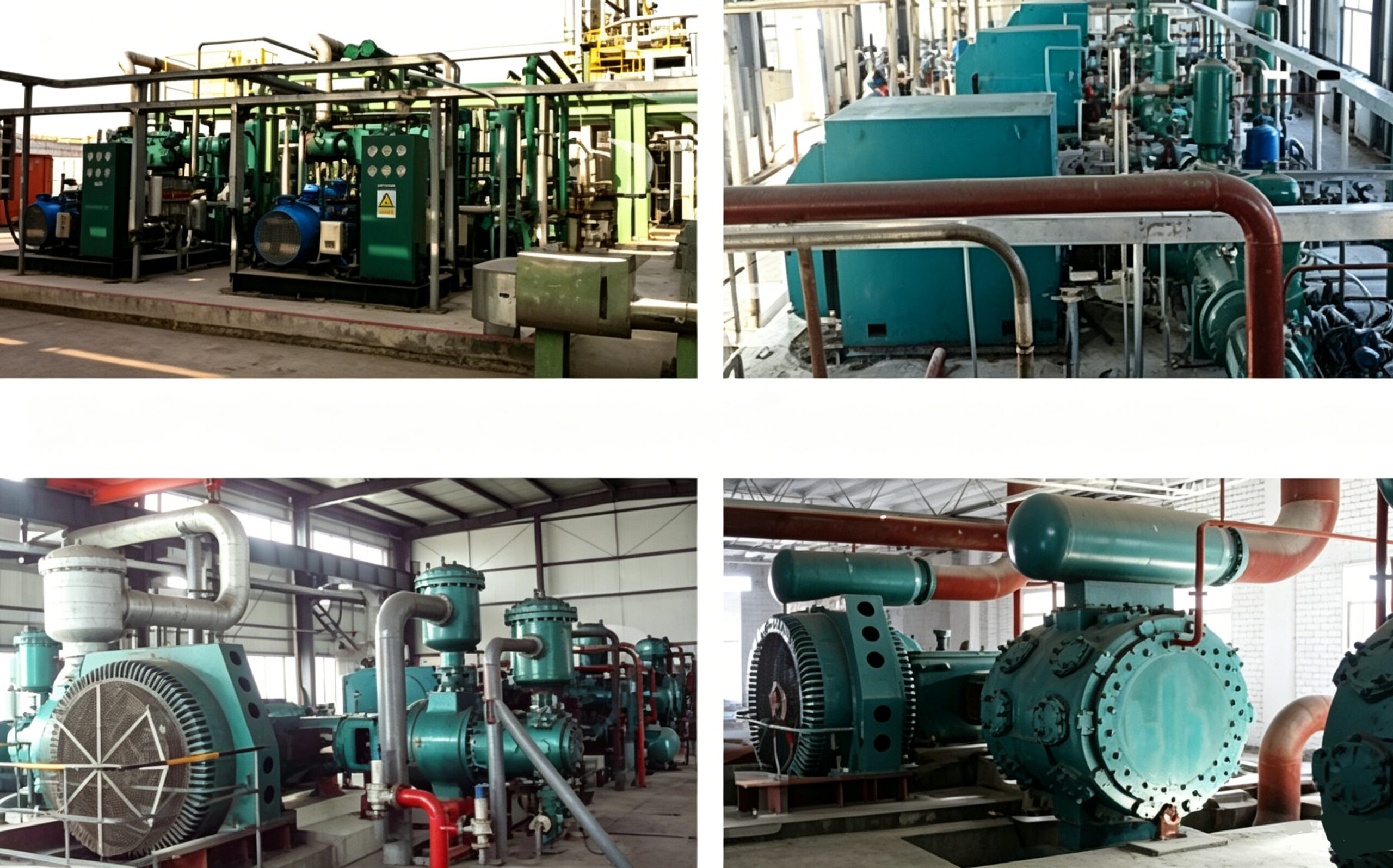
Veelgestelde vragen en selectiegids
Gerelateerde producten en oplossingen
DW-serie hogedruk stikstofcompressoren
De DW-serie is ontworpen voor persdrukken van 0,40 MPa tot 2,00 MPa en is geschikt voor stikstofinjectie, hogedrukverhoging in pijpleidingen en chemische synthese. Capaciteiten van 2 tot 130 m³/min.
ZW-serie meertraps olievrije compressoren
Verticale, meertraps olievrije compressoren voor zuurstof, stikstof, waterstof en speciale gassen. Persdrukken tot 9,00 MPa voor ultra-hogedruk gasvulling en chemische procestoepassingen.
LW-serie stikstofcompressoren met grote capaciteit
Olievrije zuigercompressoren met hoge doorstroming (20–130 m³/min) voor cryogene ASU-back-up, VPSA-booster en industriële pijpleidingdistributie. Persdrukken van 0,30 tot 0,80 MPa.
Voor een uitgebreid overzicht van onze industriële stikstofcompressor Voor ons portfolio, inclusief olievrije zuurstofcompressoren, waterstofcompressoren, koolstofdioxidecompressoren en op maat gemaakte oplossingen voor speciale gassen, kunt u contact opnemen met ons applicatieteam of onze online productcatalogus raadplegen.
Klaar om uw ultrahogedruk-stikstofsysteem te transformeren?
Onze ervaren applicatie-ingenieurs staan klaar om uw stikstofdebiet, inlaatcondities, streefwaarden voor de persdruk en beperkingen van de infrastructuur op locatie te beoordelen. Wij leveren uitgebreide technische voorstellen, ondersteuning bij het funderingsontwerp, leiding- en instrumentatiediagrammen (P&ID's), elektrische schema's en gedetailleerde analyses van de totale eigendomskosten (TCO) binnen 10 werkdagen na ontvangst van uw aanvraag.
E-mail: [email protected] | Reactie binnen 24 uur

























