
Beschrijving
4WM-100/30 stikstofcompressor – ultra-hoge capaciteit olievrije N2-booster voor industriële processen van 3,00 MPa
De 4WM-100/30 is een viertraps, vierrijige olievrije zuigercompressor voor stikstof, ontworpen om 100 m³/min te leveren bij een persdruk van 3,00 MPa. Deze compressor is speciaal ontwikkeld voor stikstofinjectie op ultragrote schaal, transport door hogedrukpijpleidingen en veeleisende petrochemische procesapplicaties. Geen olieverontreiniging, enorme doorvoer en geoptimaliseerd voor continu bedrijf bij extreme druk.
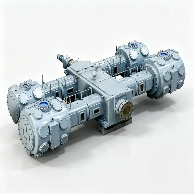
Productoverzicht
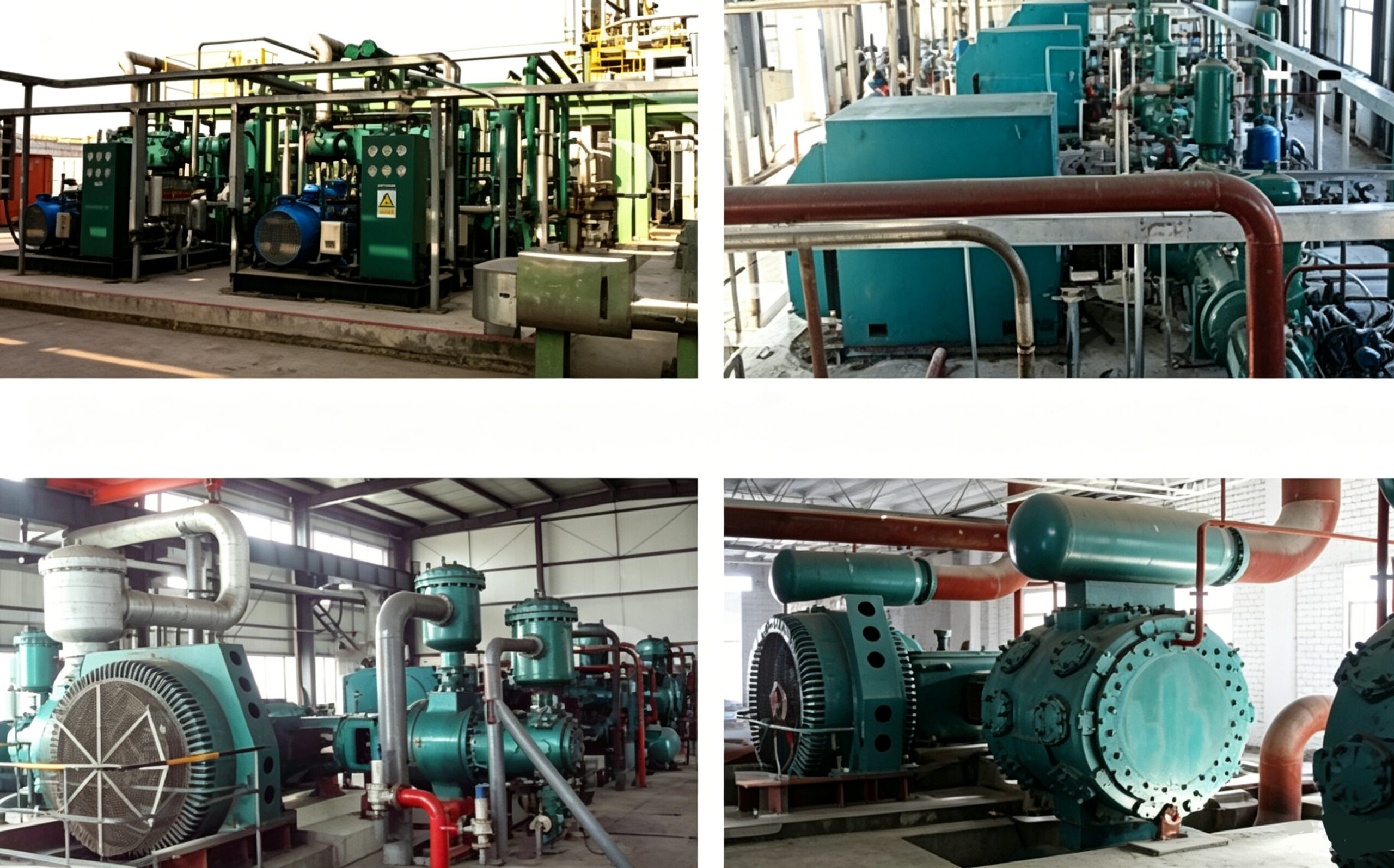
De 4WM-100/30 stikstofcompressor Dit product vertegenwoordigt het hoogtepunt van onze engineering op het gebied van olievrije zuigercompressoren en bedient het segment van ultragrote capaciteiten binnen de industriële stikstofcompressiemarkt. Met een buitengewone Capaciteit van 100 m³/min gekoppeld aan een formidabele 3,00 MPa uitlaatdrukDeze unit is ontworpen voor de meest veeleisende stikstoftoepassingen in de wereldwijde industriële gasindustrie.
Wat de 4WM-100/30 onderscheidt van alle conventionele alternatieven is zijn volledig olievrij compressiepad Gecombineerd met een thermodynamische optimalisatie in vier fasen. De zuigerveren en geleidebanden zijn vervaardigd uit geavanceerde zelfsmurende PTFE-composietmaterialen die werken zonder koolwaterstofsmeermiddelen, waardoor de stikstofstroom volledig onverontreinigd blijft, zelfs bij de extreme drukken en temperaturen die gepaard gaan met een ontlading van 3,00 MPa. Deze intrinsieke olievrije eigenschap is onmisbaar voor toepassingen met ultrazuivere stikstof in de halfgeleiderproductie, farmaceutische synthese en de productie van gas van voedselkwaliteit, waar zelfs een olieverontreiniging van minder dan 1 ppm catastrofaal zou zijn.
De compressorarchitectuur maakt gebruik van een viertraps, vier rijen (四列四级) configuratie—de meest complexe en thermodynamisch geavanceerde opstelling in ons productassortiment. Dit meertrapsontwerp verdeelt de enorme drukverhouding die nodig is om 3,00 MPa te bereiken over vier compressiecilinders, met koeling tussen elke trap. Deze gefaseerde aanpak is absoluut essentieel voor het beheersen van de extreme thermische belastingen en het behoud van de integriteit van de PTFE-afdichtingselementen, die thermisch zouden degraderen als ze zouden worden blootgesteld aan de uitlaattemperaturen van een eentraps of zelfs tweetraps compressieproces op dit drukniveau. Het robuuste gietijzeren frame en de massieve gesmede stalen krukas zijn ontworpen voor een minimale levensduur van 150.000 uur onder strikte onderhoudsprotocollen.
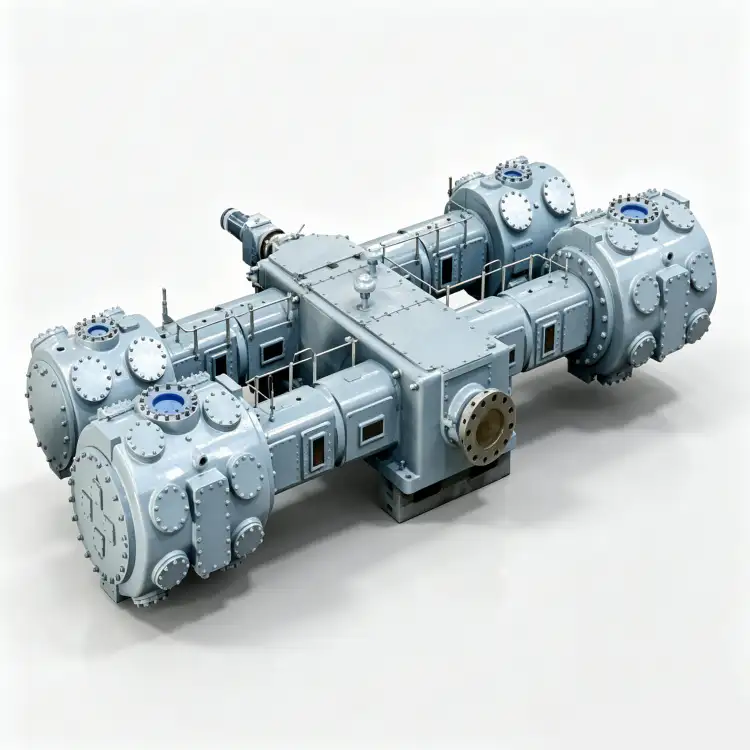
Technische specificaties – 4WM-100/30
| Parameter | Waarde | Eenheid |
|---|---|---|
| Model | 4WM-100/30 | – |
| Patroon | Viertraps, vier rijen (四列四级) | – |
| Capaciteit | 100 | m³/min |
| Afvoerdruk | 3.00 | MPa |
| Compressorafmetingen (L × B × H) | 6800 × 4000 × 3200 | mm |
| Gewicht | 36.50 | T |
| Stroom | 1200 | kW |
| Spanning | 6k of 10k | V |
| Gasmedium | Stikstof (N₂) | – |
| Smering | Olievrij | – |
* Alle specificaties zijn gebaseerd op standaard referentieomstandigheden (ISO 1217, bijlage C). De werkelijke prestaties kunnen variëren afhankelijk van de hoogte van de locatie, de omgevingstemperatuur en de inlaatcondities.
Belangrijkste kenmerken en technische voordelen
1. Viertraps thermodynamische optimalisatie voor extreme druk
De viertraps compressiearchitectuur De 4WM-100/30 is de enige thermodynamisch haalbare methode om een persdruk van 3,00 MPa te bereiken met behoud van acceptabele perstemperaturen en de integriteit van de PTFE-afdichting. Elke trap werkt met een drukverhouding van ongeveer 2,5:1 tot 3:1, met speciale buizenwarmtewisselaars tussen elke trap die de compressiewarmte afvoeren. Deze getrapte aanpak beperkt de perstemperatuur van elke trap tot onder de 145 °C, ruim binnen het veilige werkingsbereik van de PTFE-composietmaterialen. Zonder viertrapscompressie zou de perstemperatuur boven de 250 °C uitkomen, wat zou leiden tot onmiddellijke thermische degradatie van de afdichtingselementen en catastrofale compressoruitval. De vierrijige opstelling zorgt voor een uitzonderlijke krachtbalans, waarbij de tegenover elkaar geplaatste cilinders de traagheidskrachten opheffen en de trillingsoverdracht naar de fundering minimaliseren.
2. Ultra-hogetemperatuur PTFE-afdichtingstechnologie
De 4WM-100/30 maakt gebruik van een gepatenteerde technologie. zelfsmurende zuigerveer- en geleidebandassemblage Vervaardigd uit de volgende generatie PTFE-composieten, specifiek ontwikkeld voor toepassingen onder ultrahoge druk. Deze ringen zijn versterkt met hittebestendige glasvezels, bronsdeeltjes en molybdeendisulfide om een wrijvingscoëfficiënt van minder dan 0,05 te bereiken zonder externe koolwaterstofsmering. De materiaalsamenstelling is geschikt voor continu gebruik bij temperaturen tot 200 °C – hoger dan standaard PTFE-composieten – om een veiligheidsmarge te bieden tegen de verhoogde thermische belasting van viertrapscompressie. Bij een persdruk van 3,00 MPa zou de partiële druk van oliedamp buitengewoon hoog zijn, waardoor olieverontreiniging stroomafwaarts vrijwel onmogelijk te verwijderen is. Het van nature olievrije ontwerp van de 4WM-100/30 elimineert dit risico volledig. ISO 8573-1 Klasse 0-certificering zonder verdere zuiveringsapparatuur.
3. Massief, zwaar frame voor industriële lasten
Het hoofdframe is gegoten uit GG30 grijs gietijzer (hogere kwaliteit dan standaard GG25) met versterkte wandsecties tot 80 mm dik en geïntegreerde koelwaterkanalen die direct in het gietstuk zijn gefreesd. vierrijige opstelling van tegenover elkaar geplaatste cilinders Dit zorgt voor een bijna perfecte opheffing van de krachten van de eerste en tweede orde, waardoor de netto onbalanskrachten die op de fundering worden overgebracht, worden teruggebracht tot minder dan 5% van de piekgaskrachten in de cilinder. Deze uitzonderlijke mechanische balans is essentieel voor een machine van deze omvang en dit vermogen, waar onbalanskrachten anders een funderingsmassa van meer dan 100 ton zouden vereisen. De dynamisch gebalanceerde gesmede stalen krukas (42CrMo4, Q&T) wordt ondersteund door vijf hoofdlagertappen met hydrodynamische oliefilmlagers die zijn ontworpen voor de volledige levensduur van 150.000 uur.
4. Hoogspanningsmotoraandrijving voor maximale efficiëntie
De 4WM-100/30 wordt aangedreven door een 1200 kW middenspanningsinductiemotor Verkrijgbaar in 6kV- of 10kV-uitvoeringen, conform IEC 60034-1 efficiëntieklasse IE3. Bij dit vermogensniveau is middenspanningsaandrijving niet alleen gewenst, maar essentieel – een 380V-motor zou ongeveer 2000A stroom nodig hebben, wat onpraktische kabeldiameters en enorme schakelinstallaties vereist. De middenspanningsuitvoering kan direct worden geïntegreerd in industriële hoogspanningsdistributienetwerken, waardoor elektrische verliezen worden geminimaliseerd en infrastructuurkosten worden verlaagd. De motor is voorzien van een vloeistofkoelingsmantel voor gebruik in tropische klimaten en heeft isolatieklasse F met temperatuurstijgingsklasse B voor een langere levensduur.
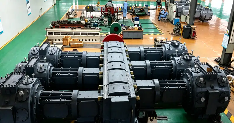
Toepassingsscenario's
Ultragrootschalige stikstofinjectie en pijpleidingtransport
In grootschalige industriële gasinstallaties en nationale stikstofpijpleidingnetwerken fungeert de 4WM-100/30 als de primaire hogedruk stikstofbooster Voor transport over lange afstanden en injectie van grote volumes. De capaciteit van 100 m³/min is gelijk aan de stikstofproductie van een cryogene luchtseparatie-eenheid (ASU) met een capaciteit van meer dan 5.000 Nm³/h, terwijl de persdruk van 3,00 MPa voldoende druk levert voor transport via pijpleidingen over afstanden van meer dan 50 km. Het olievrije ontwerp is cruciaal voor transporttoepassingen, omdat olieverontreiniging zich door het hele pijpleidingnetwerk zou verspreiden en alle afnemers stroomafwaarts zou treffen, waaronder voedselverwerkers, farmaceutische fabrikanten en halfgeleiderfabrieken.
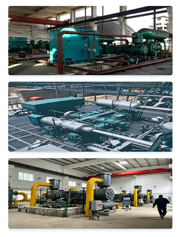
Stikstofzuivering van kolenchemie en syngas
In kolenchemische fabrieken, vergassingsinstallaties en syngasproductiecomplexen, de 4WM-100/30 stikstofcompressor levert enorme hoeveelheden stikstof onder hoge druk voor Inertisering van de vergasser, spoeling van de syngaspijpleiding en noodisolatieDe persdruk van 3,00 MPa is voldoende om de werkdruk van wervelbedvergassers (doorgaans 2,5–4,0 MPa) te overwinnen en een positieve inerte gasstroom te handhaven tijdens opstarten, uitschakelen en storingen. De capaciteit van 100 m³/min kan gelijktijdig meerdere vergassingslijnen bedienen, waardoor het aantal benodigde compressorunits wordt verminderd en de lay-out van de installatie wordt vereenvoudigd. Het olievrije ontwerp voorkomt olieverontreiniging van het synthesegas, wat de stroomafwaartse katalysatoren in methanolproductie-, Fischer-Tropsch- en ammoniakproductie-eenheden zou vergiftigen.
Verbeterde oliewinning (EOR) stikstofinjectie
Bij stikstofinjectieprojecten in olievelden voor verbeterde oliewinning comprimeert de 4WM-100/30 stikstof tot 3,00 MPa voor injectie in uitgeputte oliereservoirs. Dit zorgt voor het handhaven van de reservoirdruk en een verbeterde spoelingsefficiëntie. De enorme capaciteit van 100 m³/min maakt gelijktijdige injectie van meerdere putten mogelijk, terwijl de hoge persdruk de hydrostatische druk in diepe reservoirs overwint. Het olievrije ontwerp is essentieel voor EOR-toepassingen, omdat olieverontreiniging de reservoirformatie zou beschadigen, de permeabiliteit zou verminderen en de geproduceerde olie zou verontreinigen. De continue bedrijfscapaciteit garandeert ononderbroken injectiecampagnes die jarenlang kunnen duren.
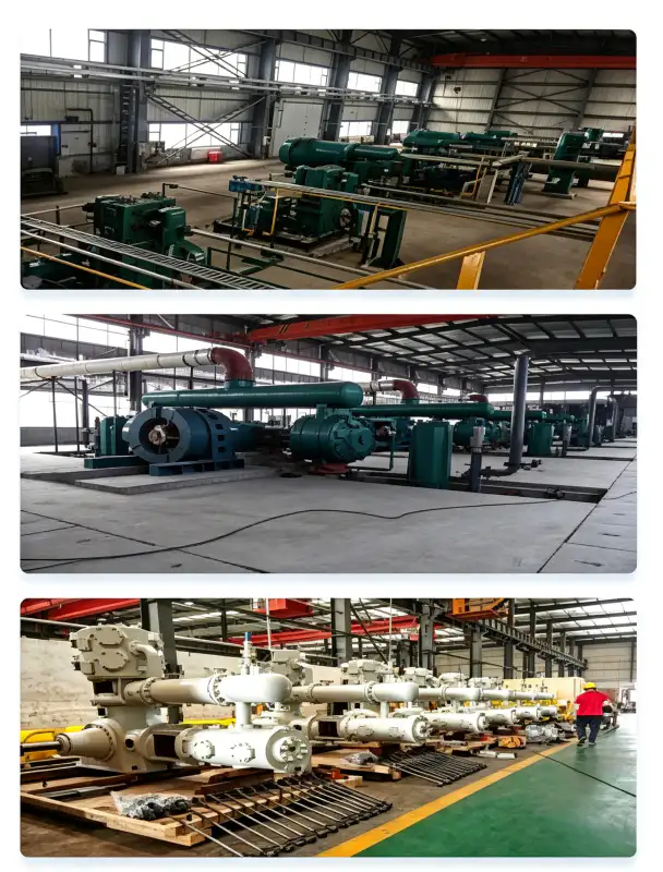
Stikstofvoorziening voor grootschalige halfgeleiderproductie
Megafabrieken die halfgeleiderwafers van 300 mm en 450 mm produceren, hebben enorme hoeveelheden ultrazuivere stikstof nodig voor spoeling van de proceskamer, atmosfeer voor wafertransport, draaggas voor chemische dampafzetting (CVD) en cryogene koelingDe capaciteit van 100 m³/min van de 4WM-100/30 kan voorzien in de stikstofbehoefte van een compleet halfgeleiderproductiecomplex, terwijl de afvoerdruk van 3,00 MPa voldoende is om stikstof door de uitgebreide verdeelleidingen en drukverlagingssystemen op de gebruikslocaties te persen. De olievrije certificering is essentieel in halfgeleidertoepassingen, waar zelfs olieverontreiniging op femtogramniveau fatale defecten kan veroorzaken in transistors op nanometerschaal.
Materiaal en constructie
De 4WM-100/30 is vervaardigd uit hoogwaardige materialen die geselecteerd zijn op hun geschiktheid voor stikstof onder ultrahoge druk, extreme thermische weerstand en structurele integriteit op industriële schaal:
| component | Materiaal | Specificatie |
|---|---|---|
| Hoofdframe | Grijs gietijzer | GG30 / HT300, 80 mm wanddikte, geïntegreerde koeling |
| Krukas | Gesmeed gelegeerd staal | 42CrMo4, Q&T, 5 hoofdlagers, ISO 1940 G1.0 gebalanceerd |
| Cilinderblokken (fase 1–4) | Grijs gietijzer | GG30, progressieve wandverdikking van LP naar HP |
| Zuigerveren | PTFE-Glas-Brons-MoS₂-composiet | Extreem hoge temperatuurbestendig, zelfsmorend, max. 200 °C |
| Rider Bands | PTFE-composiet | Zuigergeleiding, anti-slijtage, slijtagesnelheid <0,03 mm/1000 uur |
| Klepplaten | Roestvrij staal | SS316L, concentrische ring voor hoge druk, vermoeiingsbestendig |
| Intercoolers (×3) | Ketel van koolstofstaal / buizen van SS316L | ASME VIII Div.1, 1,5× hydrotest, 30 min vasthouden |
| Nakoeler | Ketel van koolstofstaal / buizen van SS316L | Hogedrukbuis met ribben, koelwater van 32 °C |
| Hogedrukleidingen | Naadloos roestvrij staal | SS316L, ANSI Klasse 900 flenzen |
| Basisframe | Gelast constructiestaal | Robuuste constructie, trillingsgedempte montage |
Alle drukdragende componenten worden ontworpen en vervaardigd in strikte overeenstemming met ASME BPVC Sectie VIII Divisie 1 of de Chinese GB 150-normen. Elke lasverbinding ondergaat een 100% röntgeninspectie (RT) volgens ASME Sectie V, Artikel 2, en elk voltooid drukvat wordt onderworpen aan een hydrostatische druktest bij 1,5 keer de maximaal toelaatbare werkdruk (MAWP) gedurende een minimale wachttijd van 30 minuten. Hogedrukleidingsystemen worden vervaardigd van naadloos SS316L met ANSI Klasse 900 flensverbindingen om lekdichtheid te garanderen bij een werkdruk van 3,00 MPa.
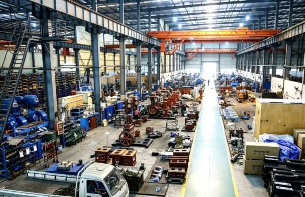
Installatie- en onderhoudsrichtlijnen
Fundament- en constructie-eisen
De 4WM-100/30 heeft een drooggewicht van 36,50 ton en een zwaartepunt op ongeveer 1200 mm boven de grondplaat. Ondanks het ontwerp met vier tegenover elkaar geplaatste cilinders dat zorgt voor een uitstekende krachtverdeling, vereisen de enorme massa en het vermogen van de machine een gewapend betonnen traagheidsblok van 60-80 tonHet blok moet worden gemonteerd op zware veerdempers (eigen frequentie 4–6 Hz) om trillingsoverdracht naar aangrenzende constructies en gevoelige instrumentatie te voorkomen. De fundering moet worden ontworpen door een gekwalificeerde constructeur om het statische gewicht plus de dynamische krachten tijdens opstarten en noodstop te kunnen dragen. Minimale vrije ruimte: 2,0 m aan alle zijden voor onderhoudstoegang, 3,0 m boven de grond voor kraantoegang tijdens grote revisies en een aparte ruimte voor zware lasten voor het verwijderen van de rotor.
Ontwerp van koelwatersystemen
De koelwaterbehoefte bedraagt ongeveer 120 m³/h bij een inlaattemperatuur van maximaal 32 °C. Het waterdistributiecircuit voorziet de cilindermantels, drie tussenkoelers en de nakoeler van water via parallelle aftakkingen met individuele debietregelkleppen. Gezien de viertrapscompressie is het beheer van het koelwater cruciaal: elke vermindering van de prestaties van de tussenkoeler zal een kettingreactie van temperatuurstijgingen in de volgende trappen veroorzaken, waardoor de veilige bedrijfstemperatuur van de PTFE-afdichtingselementen mogelijk wordt overschreden. Specificaties voor de waterkwaliteit: pH 6,5–8,5, totaal opgeloste stoffen < 400 mg/L, chloridegehalte < 30 mg/L (om corrosie van SS316L te voorkomen), zwevende deeltjes < 20 mg/L en totale hardheid < 250 mg/L als CaCO₃. Een speciaal gesloten koeltorensysteem met volledige filtratie en geautomatiseerde chemische behandeling is essentieel voor een betrouwbare werking.
Preventief onderhoudsschema
| Interval | Serviceartikel | Actie vereist |
|---|---|---|
| Dagelijks | Operationele inspectie | Controleer trillingen, lagertemperaturen, koelwaterdebieten, persdrukken (alle trappen), temperaturen |
| 250 uur | Kleppenplaatinspectie (fase 4) | Controleer de hogedrukventielen op thermische vermoeidheid, koolstofafzettingen en slijtage van de veren. |
| 500 uur | Inspectie van de klepplaat (fasen 1-3) | Controleer de afsluiters van de lagedruktrap op slijtage, afzettingen en de integriteit van de afdichting. |
| 1.000 uur | Beoordeling van de slijtage van de zuigerveren | Meet de speling in de groef van de zuigerveer op alle niveaus; vervang de veer als de speling groter is dan 0,20 mm. |
| 3.000 uur | Tussentijdse revisie | Vervang alle zuigerveren, geleidebanden en klepplaatassemblages in alle vier de fasen. |
| 6.000 uur | Grote revisie | Controleer de krukaslagertappen, meet alle lagerspelingen en vervang de hoofdlagers indien deze groter zijn dan 0,06 mm. |
Het olievrije ontwerp van de 4WM-100/30 elimineert alle oliegerelateerde onderhoudstaken die bij gesmeerde compressoren voorkomen. Er zijn geen olieverversingen nodig (een besparing van 400-600 liter per jaar), geen olieanalyseprogramma's, geen vervanging van filterelementen, geen vervanging van separatorcartridges en geen afvoer van afgewerkte olie. De belangrijkste slijtageonderdelen zijn de PTFE-zuigerveren en geleidebandendie doorgaans een levensduur van 3.000 tot 5.000 uur halen onder schone stikstofomstandigheden. Gezien de viertrapsarchitectuur moet bij de onderhoudsplanning rekening worden gehouden met de specifieke slijtagepatronen van elke trap, waarbij de hogedruktrap (trap 4) doorgaans vaker onderhoud vereist dan de lagedruktrappen.

Certificeringen voor naleving en veiligheid
De 4WM-100/30 stikstofcompressor is ontworpen, gefabriceerd en getest om te voldoen aan, of te overtreffen, de volgende internationale normen en wettelijke kaders:
ASME BPVC Sectie VIII Div.1, GB 150-2011, PED 2014/68/EU Module H (Volledige QA)
IEC 60034-1 (IE3-efficiëntie), IEC 60204-1, ISO 12100 machineveiligheid
ISO 8573-1 Klasse 0 (oliegehalte), onafhankelijk getest door TÜV Rheinland
ISO 9001:2015, ISO 14001:2015, ISO 45001:2018 (Arbeidsveiligheid en -gezondheid)
Stikstof wordt geclassificeerd als een eenvoudig verstikkend gas. Bij een persdruk van 3,00 MPa is de opgeslagen energie in het gecomprimeerde gas en de persleiding extreem hoog – een breuk kan gas vrijlaten met snelheden die de geluidssnelheid overschrijden, waardoor een onmiddellijk zuurstofarme zone ontstaat die zich over tientallen meters uitstrekt. Alle 4WM-100/30-installaties moeten het volgende omvatten: (1) Continue bewaking van zuurstoftekort in het gehele compressorgebouw en de gebieden stroomafwaarts; (2) Overdrukventielen op elke persleidingtrap met een nominale maximale toelaatbare werkdruk (MAWP) van 1101 TP3T en breekplaten als secundaire beveiliging; (3) Nooddrukontlastingssystemen die het gehele machinevolume binnen 60 seconden veilig kunnen ontluchten; (4) Explosiebestendige gebouwconstructie of buiteninstallatie met voldoende veiligheidszones; (5) Training van personeel in veiligheidsprotocollen voor gas onder ultrahoge druk. De ventilatie moet het omgevingszuurstofgehalte boven 19,51 TP3T houden volgens OSHA 29 CFR 1910.146. De noodstopvergrendelingen worden geactiveerd bij 19.5% O₂ (alarm) en zorgen voor een harde isolatie bij 18.0% O₂.
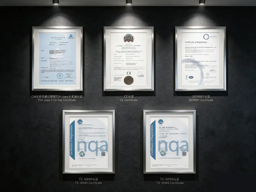
Prestatie- en efficiëntieanalyse
De 4WM-100/30 behaalt een specifiek energieverbruik van circa 12,00 kW per m³/min stikstof wordt geleverd bij een persdruk van 3,00 MPa. Dit specifieke vermogen weerspiegelt de thermodynamische realiteit van ultrahogedrukcompressie in vier trappen, waarbij de cumulatieve compressiearbeid aanzienlijk is. Binnen het segment van olievrije ultrahogedrukcompressoren (persdruk >2,50 MPa, capaciteit >50 m³/min) is dit rendement echter uitzonderlijk. Ter vergelijking: oliegesmeerde zuigercompressoren in vergelijkbare toepassingen verbruiken doorgaans 13,0–15,0 kW/m³/min, terwijl het bereiken van deze druk met schroefcompressoren meertrapsconstructies met tussenkoeling vereist, die mechanisch complex en minder efficiënt zijn.
Gedurende een jaarlijkse bedrijfscyclus van 8.000 uur levert het efficiëntievoordeel van de 4WM-100/30 ten opzichte van minder efficiënte alternatieven een rendement op van ongeveer 800.000–1.600.000 kWh aan jaarlijkse energiebesparingBij $0,08/kWh vertegenwoordigt dit een directe besparing op de elektriciteitskosten van $64.000–$128.000 per jaar. De belangrijkste economische rechtvaardiging voor de 4WM-100/30 is echter doorgaans de Een combinatie van enorme capaciteit, ultrahoge druk en een van nature olievrije werking. dat geen enkele alternatieve technologie daaraan kan tippen. totale eigendomskosten voor ultra-hogedruk stikstofcompressie Het energieverbruik en het onderhoud worden gedomineerd, en beide aspecten worden geoptimaliseerd door het olievrije ontwerp in vier fasen.
Het elimineren van oliegerelateerde verbruiksartikelen levert met name op deze schaal aanzienlijke besparingen op. Een gesmeerde compressor met een capaciteit van 100 m³/min zou jaarlijks 1.000-2.000 liter smeerolie verbruiken, plus honderden filterelementen, separatorpatronen en kosten voor de afvoer van afgewerkte olie, wat neerkomt op 1.4T25.000-1.TP4T40.000 per jaar. Het olievrije ontwerp van de 4WM-100/30 elimineert deze kosten volledig en zorgt er tegelijkertijd voor dat er geen olieverontreiniging in de stikstofproductstroom terechtkomt – een waarde die onmogelijk te kwantificeren is, maar cruciaal voor toepassingen in de halfgeleider-, farmaceutische en voedingsmiddelenindustrie.
Mogelijkheden voor maatwerk en OEM-productie
We bieden uitgebreide aanpassingsmogelijkheden om de 4WM-100/30 af te stemmen op de specifieke eisen van megaprojecten:
- Kant-en-klare EPC-pakketten: Compleet ontwerp van het compressorhuis, inclusief funderingstechniek, koelwatersystemen, elektrische onderstations, controlekamers en veiligheidssystemen. Wij begeleiden het gehele project, van ontwerp tot inbedrijfstelling.
- Redundante configuraties met twee units: Twee 4WM-100/30 compressoren geconfigureerd in een 2×100% of 3×50% opstelling met automatische lastverdeling en naadloze omschakeling. Garandeert de beschikbaarheid van 100% stikstof voor bedrijfskritische toepassingen.
- Geavanceerde DCS-integratie: Siemens S7-1500 of Allen-Bradley ControlLogix PLC met redundante processors, 15-inch HMI-touchscreens en volledige integratie met het DCS-systeem van de fabriek via OPC-UA, Modbus TCP/IP of eigen protocollen. Inclusief algoritmen voor voorspellend onderhoud en digitale tweeling-simulatie.
- Milieu- en veiligheidssystemen: Explosiebestendige compressorhuizen, gasdetectiesystemen, automatische blussystemen met blusvloeistof en nooddrukverlagingssystemen. Voldoet aan de API-, NFPA- en lokale veiligheidsvoorschriften.
- OEM- en private labelprogramma's: Op maat gemaakte branding, kleurstellingen en documentatiepakketten voor grote gasbedrijven en EPC-aannemers wereldwijd. Volledige technische ondersteuning en logistieke netwerken voor reserveonderdelen.
Aangepaste configuraties zijn beschikbaar via Minimale bestelhoeveelheid: 1 stukDe technische beoordeling en het opstellen van een voorstel nemen doorgaans 10 tot 14 werkdagen in beslag vanwege de complexiteit van de machine. De standaard levertijd bedraagt 20 tot 26 weken; versnelde programma's kunnen dit verkorten tot 16 weken voor projecten die hiervoor in aanmerking komen en waarvoor de ontwerpen al zijn goedgekeurd.
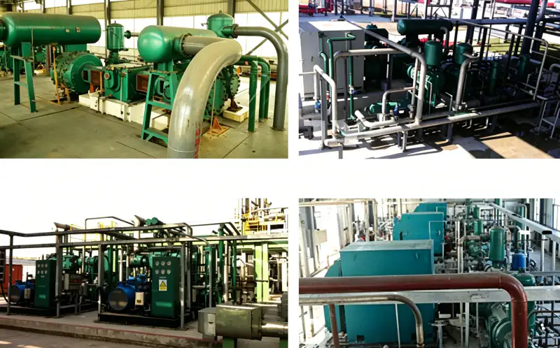
Casestudie: Geïntegreerde stikstofvoorziening voor een kolenchemisch complex
Cliënt: Een staatsbedrijf in de kolenchemie in China exploiteert vier wervelbedvergassers en een daaropvolgende methanol-/ammoniaksynthese-installatie.
Uitdaging: Het complex had 90.000 Nm³/u hogedrukstikstof (2,8–3,2 MPa) nodig voor het inertiseren van de vergasser, het spoelen van de syngaspijpleiding, het conserveren van de katalysator en noodafsluiting. De bestaande toevoer bestond uit drie oliegesmeerde compressoren (Europees merk, meer dan 20 jaar in gebruik) die te kampen hadden met catastrofale olieverontreiniging in de stikstofstroom. De olieverontreiniging vergiftigde de methanolsynthesekatalysatoren (vervangingskosten $2.5M per lading), vervuilde de syngaswarmtewisselaars en veroorzaakte ongeplande stilstanden van gemiddeld 45 uur per jaar. De verouderde compressoren waren bovendien energie-inefficiënt en verbruikten 1450 kW per 100 m³/min, vergeleken met moderne normen.
Oplossing: Wij leverden twee 4WM-100/30 olievrije stikstofcompressoren In een redundante configuratie van 2 × 100%-compressoren, elk op een eigen, kant-en-klaar platform met geïntegreerde viertraps tussenkoeling, nakoeling en redundante Siemens S7-1500 PLC-besturingssystemen. De compressoren waren ondergebracht in een explosiebestendig gebouw met automatische gasdetectie, noodontluchting en brandbestrijding. Stroomopwaarts was een buffervat van 50 m³ geïnstalleerd om vraagfluctuaties van de vier vergassingsinstallaties op te vangen.
Gekwantificeerde resultaten na 36 maanden:
- Stikstofgehalte van de olie: Verlaagd van 5,8 mg/m³ naar <0,01 mg/m³, waarbij ISO 8573-1 Klasse 0 is behaald
- Vergiftigingsincidenten met methanolkatalysatoren: Nul Sinds de ingebruikname is er per vermeden katalysatorvervanging een besparing van $2,5M gerealiseerd.
- Ongeplande shutdowns: Verminderd van 45 uur per jaar naar 2 uur per jaar. (alleen tijdens gepland onderhoud)
- Energieverbruik: Verbeterd met 17,2% (van 1.450 tot 1.200 kW per 100 m³/min), besparing van $320.000/jaar per compressor
- Beschikbaarheid van compressoren: 99.7% meer dan 36 maanden met redundante configuratie
- Terugverdienperiode: 3,2 jaar waaronder energiebesparing, bescherming van de katalysator en vermeden verliezen door stilstand.
“De 4WM-100/30 compressoren hebben onze stikstofvoorziening getransformeerd van een chronisch operationeel risico naar een betrouwbare voorziening. De eliminatie van olieverontreiniging heeft zichzelf al vele malen terugverdiend, alleen al door de bescherming van de katalysator. De redundantie geeft ons het vertrouwen dat we nooit zonder stikstofvoorziening voor onze vergassers zullen komen te zitten.” — Chief Operations Officer, Coal Chemical Enterprise
Veelgestelde vragen en selectiegids
Gerelateerde producten en oplossingen
DW-serie hogedruk stikstofcompressoren
De DW-serie is ontworpen voor persdrukken van 0,40 MPa tot 2,00 MPa en is geschikt voor stikstofinjectie, hogedrukverhoging in pijpleidingen en chemische synthese. Capaciteiten variëren van 2 tot 130 m³/min met tweetraps- en meertrapsconfiguraties.
ZW-serie meertraps olievrije compressoren
Verticale, meertraps olievrije compressoren voor zuurstof, stikstof, waterstof en speciale gassen. Persdrukken tot 9,00 MPa voor ultra-hogedruk gasvulling en chemische procestoepassingen.
LW-serie stikstofcompressoren met grote capaciteit
Olievrije zuigercompressoren met hoge doorstroming (20–130 m³/min) voor cryogene ASU-back-up, VPSA-booster en industriële pijpleidingdistributie. Persdrukken van 0,30 tot 0,80 MPa.
Voor een uitgebreid overzicht van onze industriële stikstofcompressor Voor ons portfolio, inclusief olievrije zuurstofcompressoren, waterstofcompressoren, koolstofdioxidecompressoren en op maat gemaakte oplossingen voor speciale gassen, kunt u contact opnemen met ons applicatieteam of onze online productcatalogus raadplegen.
Bent u klaar om uw eigen ultra-hogedruk stikstofoplossing te ontwikkelen?
Onze ervaren applicatie-ingenieurs en projectmanagers staan klaar om uw stikstofdebiet, drukspecificaties, locatiebeperkingen en integratiebehoeften te beoordelen. Wij leveren uitgebreide haalbaarheidsstudies, gedetailleerde technische voorstellen, funderings- en gebouwontwerp, leiding- en instrumentatiediagrammen (P&ID's) en complete turnkey EPC-oplossingen voor projecten van elke omvang.
E-mail: [email protected] | Reactie binnen 24 uur

























