توضیحات
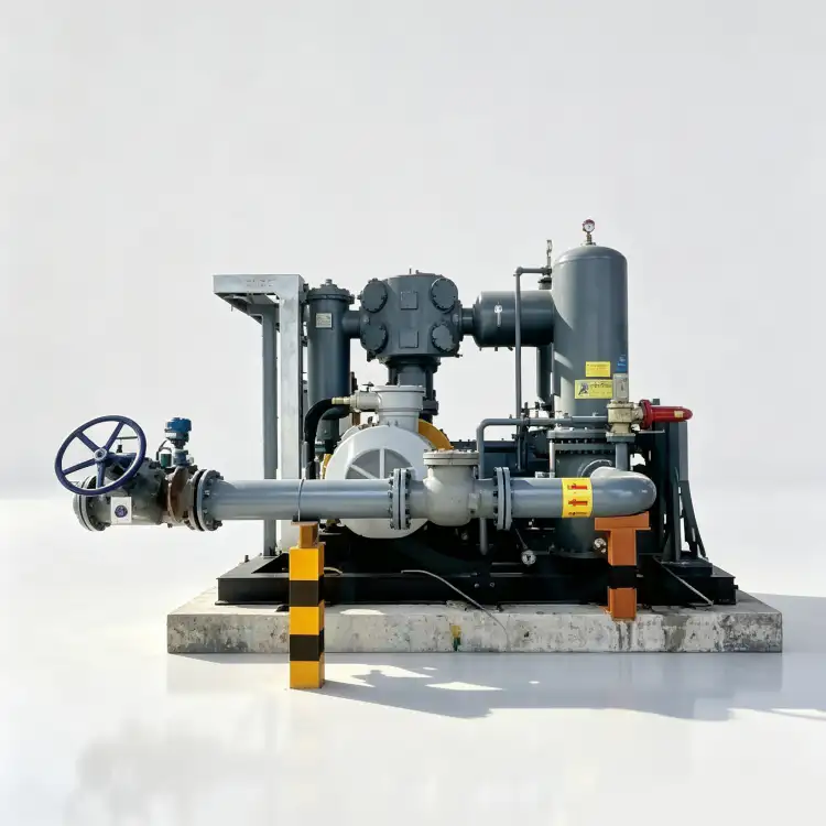
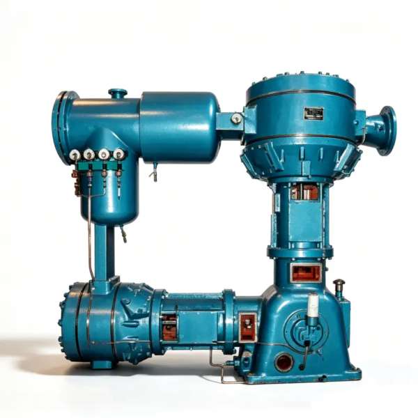
کمپرسور نیتروژن LW-33/30 – بوستر نیتروژن بدون روغن با ظرفیت بالا برای کاربردهای صنعتی با فشار فوق العاده بالا 3.00 مگاپاسکال
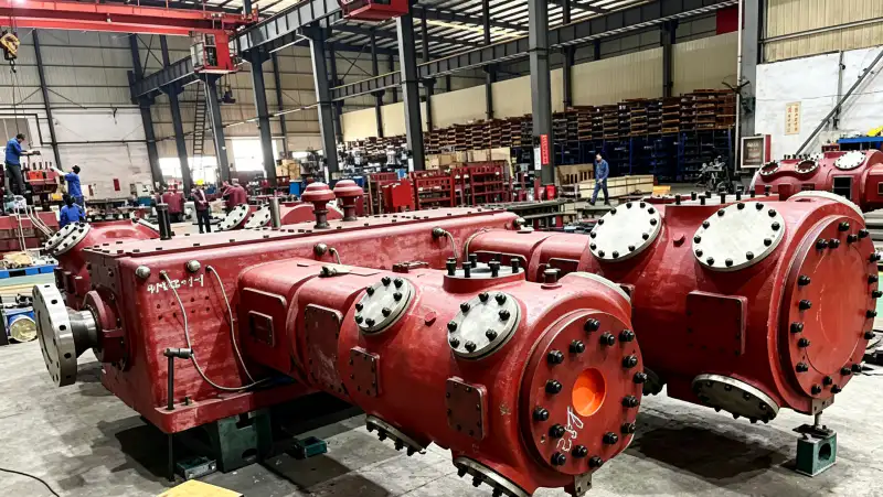
کمپرسور نیتروژن پیستونی دو مرحلهای سه ردیفه بدون روغن LW-33/30 که برای ارائه دبی ۳۳ متر مکعب در دقیقه با فشار تخلیه ۳ مگاپاسکال طراحی شده است، برای تزریق نیتروژن با فشار بسیار بالا، سیستمهای مایعسازی گاز و کاربردهای فرآیند پتروشیمی دشوار طراحی شده است. آلودگی روغن صفر، ساختار سنگین و بهینه شده برای عملکرد مداوم در فشار بسیار بالا.
نمای کلی محصول
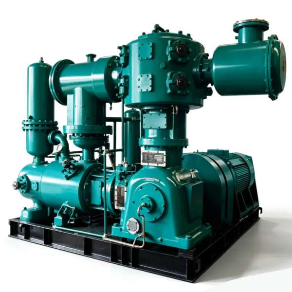
The کمپرسور نیتروژن LW-33/30 این کمپرسور، دستاوردی برجسته در سبد محصولات کمپرسور پیستونی بدون روغن ما محسوب میشود که برای دشوارترین کاربردهای نیتروژن با فشار فوق بالا در زیرساختهای گاز صنعتی مهندسی شده است. با ظرفیت قابل توجهی از ۳۳ متر مکعب در دقیقه و استثنایی فشار تخلیه ۳.۰۰ مگاپاسکالاین واحد بخش فشار فوق بالا از طیف محصولات ما را اشغال میکند و به کاربردهایی که به نیتروژن در فشارهایی بسیار فراتر از سطوح توزیع مرسوم نیاز دارند، خدمات ارائه میدهد.
چیزی که LW-33/30 را متمایز میکند، ... مسیر فشردهسازی کاملاً بدون روغن همراه با توانایی ارائه جریان عظیم در فشار بسیار بالا. حلقههای پیستون و نوارهای رادیال با دقت از مواد کامپوزیت PTFE پیشرفته خود روانکننده ساخته شدهاند که بدون هیچ روانکننده هیدروکربنی کار میکنند و تضمین میکنند که جریان نیتروژن کاملاً عاری از آلودگی روغن باقی بماند. در فشار 3.00 مگاپاسکال، حتی آلودگی روغن ناچیز نیز بسیار غلیظ و حذف آن در پایین دست بسیار دشوار خواهد بود، که این امر طراحی بدون روغن بومی را نه تنها مفید، بلکه برای کاربردهای با خلوص بالا کاملاً اجباری میکند.
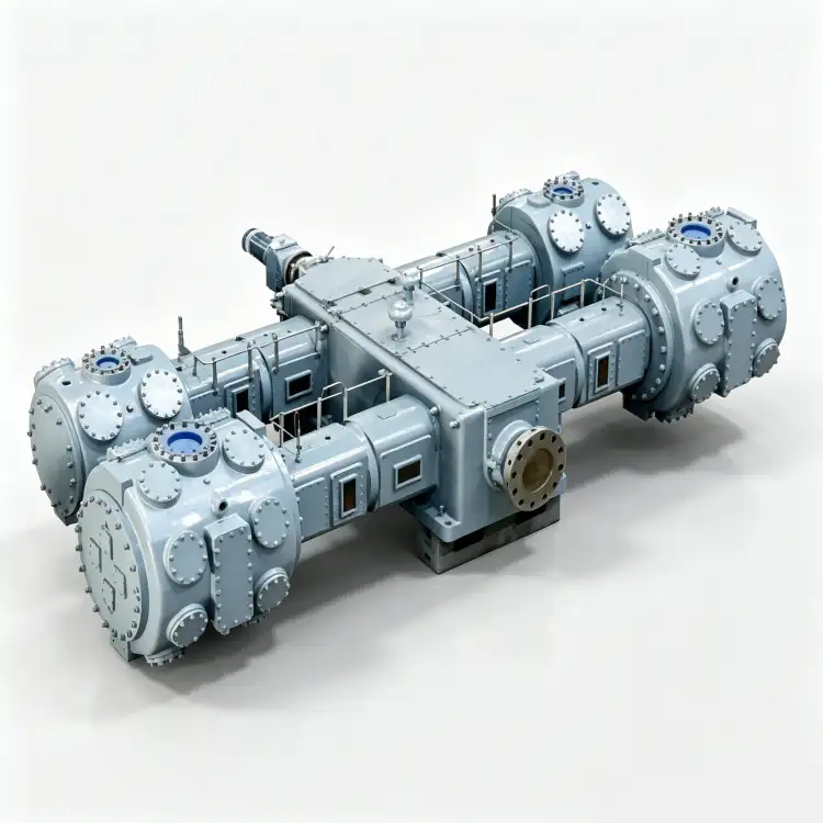
معماری کمپرسور از یک دو مرحله ای، سه ردیفی (二列三级) پیکربندی که برای مدیریت نسبت فشار شدید مورد نیاز برای دستیابی به فشار تخلیه 3.00 مگاپاسکال ضروری است. چیدمان سه ردیفه، تعادل نیروی برتر و لرزش کمتری را در مقایسه با طرحهای تک ردیفه فراهم میکند، در حالی که فشردهسازی دو مرحلهای، راندمان ترمودینامیکی و دمای تخلیه قابل مدیریت را تضمین میکند. هر مرحله دارای خنککننده داخلی مستقل است که یکپارچگی عناصر آببندی PTFE را حتی تحت تنش حرارتی عملکرد فوق فشار بالا حفظ میکند. قاب چدنی تقویتشده و میللنگ فولادی فورجشده سنگین برای حداقل عمر مفید ارزیابی شدهاند. ۱۲۰،۰۰۰ ساعت تحت پروتکلهای استاندارد نگهداری.
مشخصات فنی – LW-33/30
| پارامتر | ارزش | واحد |
|---|---|---|
| مدل | LW-33/30 | – |
| الگو | دو مرحله ای، سه ردیفی (二列三级) | – |
| ظرفیت | 33 | متر مکعب در دقیقه |
| فشار تخلیه | 3.00 | مگاپاسکال |
| اندازه کمپرسور (طول × عرض × ارتفاع) | ۳۱۶۰ × ۱۶۸۵ × ۲۴۴۰ | میلیمتر |
| وزن | 6.60 | تی |
| قدرت | 350 | کیلووات |
| ولتاژ | ۶ هزار یا ۱۰ هزار | پنجم |
| گاز متوسط | نیتروژن (N₂) | – |
| روانکاری | بدون روغن | – |
* تمام مشخصات در شرایط مرجع استاندارد (ISO 1217، پیوست C) رتبهبندی شدهاند. عملکرد واقعی ممکن است بر اساس ارتفاع محل، دمای محیط و شرایط ورودی متفاوت باشد.
ویژگیهای کلیدی و مزایای مهندسی
۱. سیستم آببندی PTFE بدون روغن با فشار بسیار بالا
LW-33/30 از یک سیستم اختصاصی بهره میبرد. مجموعه رینگ پیستون و باند رادیال خود روان کننده ساخته شده از کامپوزیتهای PTFE با عملکرد فوقالعاده بالا که با الیاف شیشه، الیاف کربن و ذرات برنز تقویت شدهاند. این فرمولاسیون پیشرفته مواد، بدون هیچ گونه روانکاری هیدروکربنی خارجی، ضریب اصطکاک زیر 0.05 را به دست میآورد و تضمین میکند که جریان نیتروژن حتی در فشار تخلیه 3.00 مگاپاسکال کاملاً عاری از آلودگی روغن باقی بماند. در این فشار بسیار بالا، فشار جزئی هرگونه بخار روغن تقریباً 10 برابر بیشتر از 0.30 مگاپاسکال خواهد بود و حذف روغن در پایین دست را عملاً غیرممکن میکند. فرمولاسیون PTFE برای عملکرد مداوم در دماهای تا 190 درجه سانتیگراد رتبهبندی شده است و یکپارچگی آببندی قابل اعتماد را تحت تنش حرارتی شدید فشردهسازی با فشار بسیار بالا تضمین میکند.
۲. تعادل نیرو در سه ردیف برای پایداری در برابر فشارهای شدید
The آرایش سیلندرهای سه ردیفه در خلاف جهت هم کمپرسور LW-33/30 حذف نیروهای مرتبه اول و مرتبه دوم استثنایی را فراهم میکند و نیروهای اینرسی نامتعادل منتقل شده به فونداسیون را در مقایسه با طرحهای تک ردیفه بیش از 90% کاهش میدهد. در فشار تخلیه 3.00 مگاپاسکال، حداکثر نیروهای گاز روی پیستونها به طور قابل توجهی بالاتر از کمپرسورهای معمولی هستند و تعادل نیرو را به یک ملاحظه طراحی حیاتی تبدیل میکنند. پیکربندی سه ردیفه این نیروها را در چندین سیلندر توزیع میکند، انتقال ارتعاش را به حداقل میرساند و به کمپرسور اجازه میدهد بدون نیاز به سیستمهای ایزوله ارتعاش تخصصی، روی یک بلوک اینرسی بتن مسلح استاندارد کار کند. این پایداری مکانیکی برای عملکرد مداوم در محیطهای صنعتی 24 ساعته و 7 روز هفته ضروری است.
۳. فشردهسازی دو مرحلهای با خنککننده داخلی پیشرفته
The معماری فشردهسازی دو مرحلهای از نظر ترمودینامیکی برای دستیابی به هدف فشار تخلیه ۳.۰۰ مگاپاسکال ضروری است. نسبت فشار کلی تقریباً ۳۰:۱ تا ۶۰:۱ (بسته به شرایط ورودی) بین یک مرحله فشار پایین و یک مرحله فشار بالا تقسیم میشود و هر مرحله با نسبت فشار قابل کنترلی کار میکند. یک اینترکولر پوسته و لوله با ظرفیت بالا بین مراحل، گرمای قابل توجه فشردهسازی را حذف میکند، دمای تخلیه را زیر ۱۶۰ درجه سانتیگراد نگه میدارد و از تخریب حرارتی عناصر آببندی PTFE جلوگیری میکند. اینترکولر نسبت به ظرفیت کمپرسور بزرگتر از اندازه واقعی است تا حاشیه خنککنندگی کافی را حتی در شرایط محیطی تابستان یا دمای آب خنککننده حاشیهای تضمین کند.
۴. درایو ولتاژ متوسط برای یکپارچهسازی صنعتی توان بالا
LW-33/30 توسط یک رانده میشود. موتور القایی ولتاژ متوسط ۳۵۰ کیلووات در پیکربندیهای 6 کیلوولت یا 10 کیلوولت، مطابق با کلاس راندمان IEC 60034-1 IE3 موجود است. درایو ولتاژ متوسط برای موتوری با این توان ضروری است و نیاز به تابلوهای ولتاژ پایین بزرگ و کابلکشی سنگین را که برای معادل 380 ولت مورد نیاز است، از بین میبرد. ادغام مستقیم در شبکههای توزیع ولتاژ متوسط صنعتی، هزینههای زیرساخت برق را کاهش میدهد، تلفات I²R در کابلکشی برق را به حداقل میرساند و راندمان کلی انرژی را بهبود میبخشد. این موتور مجهز به یک سیستم یاتاقان قوی است که برای بارهای شعاعی و محوری مرتبط با عملکرد کمپرسور فشار قوی طراحی شده است.
سناریوهای کاربردی
تزریق نیتروژن با فشار فوق العاده بالا برای نفت و گاز
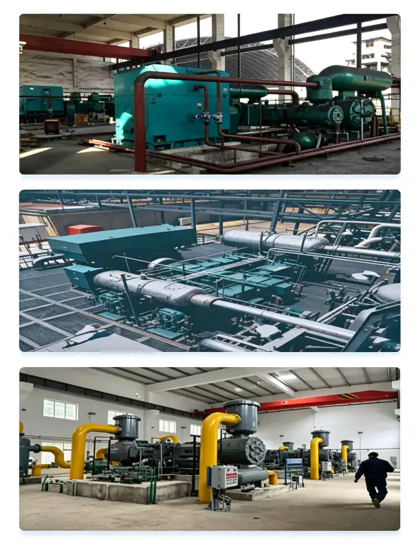
در عملیات تولید نفت و گاز، LW-33/30 فراهم میکند. نیتروژن با فشار بالا برای ازدیاد برداشت نفت (EOR)، عملیات فرازآوری با گاز و تحریک چاهفشار تخلیه ۳.۰۰ مگاپاسکال برای تزریق نیتروژن به مخازن در اعماق تا ۲۰۰۰ متر، جایی که فشارهای سازند برای دستیابی به جابجایی مؤثر نیاز به فشارهای تزریق بالا دارند، کافی است. ظرفیت ۳۳ متر مکعب در دقیقه میتواند به طور همزمان چندین چاه تزریق را از طریق یک سیستم توزیع نیتروژن با فشار بالا و متمرکز تغذیه کند. طراحی بدون روغن در کاربردهای میدان نفتی بسیار مهم است زیرا هرگونه آلودگی نفتی، ترشوندگی سنگ مخزن را تغییر میدهد، راندمان بازیابی نفت را کاهش میدهد و به طور بالقوه باعث آسیب به سازند میشود.
سیستمهای تقویت مایعسازی گاز در مقیاس بزرگ
در کارخانههای مایعسازی نیتروژن و تأسیسات فرآوری گاز کرایوژنیک، تقویت کننده نیتروژن LW-33/30 نیتروژن را از تبخیرکننده مایعساز یا سیستم ذخیرهسازی تا فشار بالای مورد نیاز برای توزیع، پردازش بیشتر یا تزریق مجدد به چرخه مایعسازی فشرده میکند. فشار تخلیه ۳.۰۰ مگاپاسکال برای هدایت نیتروژن از طریق مبدلهای حرارتی فشار بالا، توربینهای انبساطی و تجهیزات فرآیندی که در فشارهای بالا کار میکنند، کافی است. طراحی بدون روغن از آلودگی تجهیزات کرایوژنیک جلوگیری میکند، جایی که حتی مقدار کمی روغن میتواند منجمد شود و مجاری مبدل حرارتی را مسدود کند و باعث اختلالات فاجعهبار فرآیند شود.
نیتروژن فرآیند فشار فوق العاده بالای پتروشیمی
در عملیات پتروشیمی و پالایشگاهی، LW-33/30 نیتروژن فوق فشار بالا را برای ... فراهم میکند. بیاثرسازی راکتور فشار بالا، احیای کاتالیزور، کاهش فشار اضطراری و آزمایش فشار خط لولهفشار تخلیه ۳.۰۰ مگاپاسکال برای تزریق نیتروژن به مخازن فرآیندی که در فشارهای تا ۲.۵ مگاپاسکال کار میکنند، کافی است و پوششهای گاز بیاثر مثبت را در تمام مراحل عملیاتی حفظ میکند. رتبهبندی کار مداوم، دسترسی بدون وقفه به نیتروژن را در طول دورههای طولانی چرخش تضمین میکند. گواهینامه بدون روغن برای کاربردهای پتروشیمی که در آن نیتروژن با بسترهای کاتالیزور تماس میگیرد یا وارد جریانهای فرآیندی میشود که باید کاملاً عاری از هیدروکربن باقی بمانند، الزامی است.
تولید برق و بیاثر کردن توربین
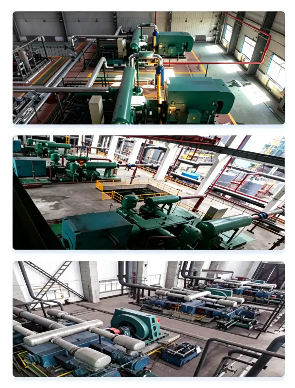
نیروگاههای گازی و تأسیسات سیکل ترکیبی برای ... به نیتروژن با فشار بالا نیاز دارند. بیاثر کردن روتور توربین گازی، پاکسازی محفظه احتراق و حفظ HRSG (مولد بخار بازیابی حرارت) در طول دورههای خاموشی. فشار تخلیه ۳.۰۰ مگاپاسکال LW-33/30 برای راندن نیتروژن از طریق مجاری داخلی پیچیده توربینهای گازی بزرگ و حفظ فشار مثبت در دستههای لوله HRSG در طول خاموشیهای طولانی مدت کافی است. ظرفیت جریان بالا میتواند به چندین توربین در یک مجتمع تولید برق واحد خدمات ارائه دهد، تعداد واحدهای کمپرسور مورد نیاز را کاهش داده و تدارکات تعمیر و نگهداری را ساده کند.
مواد و ساخت و ساز
LW-33/30 از مواد ممتازی ساخته شده است که برای سازگاری با نیتروژن در فشار بسیار بالا، مقاومت حرارتی شدید و عمر عملیاتی طولانی انتخاب شدهاند:
| کامپوننت | مواد | مشخصات |
|---|---|---|
| بلوک سیلندر (LP) | چدن خاکستری | GG25 / HT250، ضخامت دیواره تقویت شده |
| بلوک سیلندر (HP) | چدن خاکستری | GG25 / HT250، تقویتشده با استحکام بالا + شیاردار |
| میل لنگ | فولاد آلیاژی آهنگری شده | 42CrMo4، Q&T، ISO 1940 G2.5 بالانس دینامیکی |
| حلقههای پیستون | کامپوزیت PTFE-شیشه-کربن-برنز | دارای درجهبندی فشار فوق العاده بالا، خود روان کننده، حداکثر ۱۹۰ درجه سانتیگراد |
| گروههای سوارکاری | کامپوزیت PTFE | هدایت پیستون، ضد سایش، نرخ سایش <0.03 میلیمتر در 1000 ساعت |
| صفحات سوپاپ | فولاد ضد زنگ | SS316، طراحی حلقه متحدالمرکز با فشار فوق العاده بالا |
| میلههای اتصال | فولاد آهنگری شده با یاتاقانهای بابیت | سنگین، ماشینکاری دقیق، روغنکاری شده |
| اینترکولر | لولههای فولادی کربنی / SS316 | ASME VIII Div.1، ظرفیت بیش از حد بزرگ، هیدروتست ۱.۵ برابر |
| پسسردکن | لولههای فولادی کربنی / SS316 | لوله پرهدار فشار بالا، دمای آب خنککننده ۳۲ درجه سانتیگراد |
| لوله کشی فشار قوی | فولاد ضد زنگ بدون درز | فلنجهای SS316، ANSI کلاس 900 |
| قاب پایه | فولاد سازهای سنگین | ساخت جوش داده شده، نصب با میرایی ارتعاش |
تمام اجزای تحمل فشار مطابق با الزامات طراحی و ساخته میشوند. بخش 1 ASME BPVC بخش VIII یا استانداردهای GB 150 چین. هر اتصال جوش طبق ماده 2 بخش V استاندارد ASME، تحت بازرسی رادیوگرافی (RT) 100% قرار میگیرد و هر مخزن تحت فشار تکمیلشده تحت آزمایش فشار هیدرواستاتیک با 1.5 برابر حداکثر فشار کاری مجاز (MAWP) به مدت حداقل 30 دقیقه قرار میگیرد. سیستمهای لولهکشی فشار بالا از فولاد ضد زنگ بدون درز SS316 با اتصالات فلنجی ANSI Class 900 ساخته میشوند تا از عدم نشتی در فشار عملیاتی 3.00 مگاپاسکال اطمینان حاصل شود.
دستورالعملهای نصب و نگهداری
الزامات فونداسیون و سازه
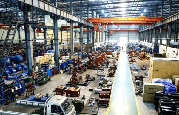
وزن خالص LW-33/30 معادل ۶.۶۰ تن و مرکز ثقل آن تقریباً ۹۵۰ میلیمتر بالاتر از صفحه پایه است. طراحی سه ردیف سیلندر متقابل، تعادل نیروی فوقالعادهای را فراهم میکند و امکان نصب روی ... را فراهم میکند. بلوک اینرسی بتن مسلح ۱۲ تا ۱۵ تنیاین بلوک باید روی لرزهگیرهای الاستومری (فرکانس طبیعی ۶ تا ۸ هرتز) نصب شود. حداقل فضای مورد نیاز: ۱.۵ متر در سمت غیر محرک برای دسترسی به شیر، ۱.۲ متر در سمت محرک برای نگهداری موتور و ۲ متر فضای بالای سر برای دسترسی به جرثقیل در طول تعمیرات اساسی. لولهکشی تخلیه فشار بالا باید به درستی با آویزهای فنری پشتیبانی شده و برای جلوگیری از خستگی ناشی از ارتعاش در فشار ۳ مگاپاسکال مهار شود. تمام تکیهگاههای لولهکشی باید طوری طراحی شوند که انبساط حرارتی را در طول چرخههای راهاندازی و خاموش شدن در خود جای دهند.
طراحی سیستم آب خنک کننده
تقاضای آب خنک کننده تقریباً است ۴۰ متر مکعب در ساعت در دمای ورودی که از ۳۲ درجه سانتیگراد تجاوز نمیکند. مدار توزیع آب، ژاکتهای سیلندر، اینترکولر و افترکولر را در شاخههای موازی با شیرهای کنترل جریان جداگانه تغذیه میکند. با توجه به نسبت فشار شدید، اینترکولر نسبت به ظرفیت کمپرسور بزرگتر از حد معمول در نظر گرفته شده است تا حاشیه خنککنندگی کافی تضمین شود. مشخصات کیفیت آب: pH 6.5-8.5، کل جامدات محلول < ۵۰۰ میلیگرم در لیتر، میزان کلرید < ۵۰ میلیگرم در لیتر (برای جلوگیری از خوردگی لوله SS316)، جامدات معلق < ۳۰ میلیگرم در لیتر و سختی کل < ۳۰۰ میلیگرم در لیتر به صورت CaCO₃. یک برج خنککننده حلقه بسته با فیلتراسیون جریان جانبی و تصفیه شیمیایی برای همه تاسیسات اکیداً توصیه میشود تا کیفیت ثابت آب خنککننده تضمین شود.
برنامه نگهداری پیشگیرانه
| فاصله | مورد خدمات | اقدام لازم |
|---|---|---|
| روزانه | بازرسی عملیاتی | سطح ارتعاش، صدای غیرعادی، جریان آب خنککننده، فشار تخلیه و دما را بررسی کنید. |
| ۲۵۰ ساعت | بازرسی صفحه شیر | شیرهای مکش/دهش را از نظر رسوبات کربنی، فرسودگی فنر و ترک خوردگی باز کرده و بررسی کنید. |
| ۱۰۰۰ ساعت | ارزیابی سایش رینگ پیستون | فاصله شیار رینگ را اندازه بگیرید؛ اگر فاصله بیش از 0.20 میلیمتر بود، رینگها را تعویض کنید. |
| ۳۰۰۰ ساعت | تعمیرات اساسی میانی | تمام رینگهای پیستون، تسمههای رادیال و مجموعههای صفحه سوپاپ را تعویض کنید |
| ۶۰۰۰ ساعت | تعمیرات اساسی | یاتاقانهای میللنگ را بررسی کنید، لقی یاتاقانهای اصلی را اندازهگیری کنید، در صورت بزرگتر از 0.08 میلیمتر بودن، یاتاقانها را تعویض کنید. |
طراحی بدون روغن LW-33/30 در مقایسه با نمونههای روغنکاریشده، تعمیر و نگهداری را به طرز چشمگیری ساده میکند. نیازی به تعویض روغن، آنالیز روغن، تعویض فیلتر و تعویض کارتریج جداکننده نیست. اقلام مصرفی اصلی عبارتند از حلقههای پیستون و نوارهای پیستونی PTFEکه معمولاً در شرایط نیتروژن تمیز و فشار فوق العاده بالا به 3000 تا 5000 ساعت عمر مفید میرسند. صفحات شیر فشار بالا ممکن است به دلیل فشار مکانیکی شدید در 3.00 مگاپاسکال، نیاز به بازرسی مکرر بیشتری نسبت به معادلهای فشار پایین داشته باشند، اما بار کلی نگهداری به طور قابل توجهی کمتر از سیستمهای روغنکاری شده با روغن باقی میماند.

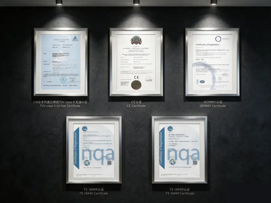
گواهینامههای انطباق و ایمنی
کمپرسور نیتروژن LW-33/30 به گونهای طراحی، تولید و آزمایش شده است که استانداردهای بینالمللی و چارچوبهای نظارتی زیر را برآورده کرده یا از آنها فراتر رود:
ASME BPVC Section VIII Div.1, GB 150-2011, PED 2014/68/EU Module A
IEC 60034-1 (راندمان IE3)، IEC 60204-1، ISO 12100 ایمنی ماشین آلات
ISO 8573-1 کلاس 0 (میزان روغن)، آزمایش شده به طور مستقل توسط TÜV Rheinland
ایزو ۹۰۰۱:۲۰۱۵، ایزو ۱۴۰۰۱:۲۰۱۵
نیتروژن به عنوان یک گاز خفه کننده ساده طبقه بندی می شود. در فشار تخلیه ۳.۰۰ مگاپاسکال، خطر انتشار سریع گاز و جابجایی اکسیژن بسیار بالا است. تمام تاسیسات LW-33/30 باید نظارت مداوم بر کمبود اکسیژن در اتاق کمپرسور و تمام مناطق مجاور را در نظر بگیرند. لوله کشی تخلیه فشار بالا باید به شیرهای اطمینان با درجه ۱۱۰۱TP3T از MAWP و دیسک های راپچر به عنوان حفاظت ثانویه مجهز شود. تمام لوله کشی های فشار بالا باید مطابق با ASME B31.3 (لوله کشی فرآیند) طراحی، ساخته و بازرسی شوند. سیستم های تهویه باید اکسیژن محیط را بالاتر از ۱۹.۵۱TP3T طبق OSHA 29 CFR 1910.146 نگه دارند. قفل های خاموش کننده اضطراری باید در ۱۹.۵۱TP3T O₂ (هشدار) فعال شوند و در ۱۸.۰۱TP3T O₂ (خاموش کننده سخت) ایزولاسیون خودکار را آغاز کنند. پرسنل قبل از کار یا نگهداری این تجهیزات باید در مورد پروتکل های ایمنی گاز فوق فشار بالا آموزش ببینند. سیستمهای نیتروژن با فشار بالا باید به وضوح برچسبگذاری شده و از نظر فیزیکی از مناطق کمفشار جدا باشند.
تحلیل عملکرد و کارایی
LW-33/30 به ... دست مییابد. مصرف برق ویژه تقریباً 10.61 کیلووات بر متر مکعب بر دقیقه نیتروژن تحویل داده شده در فشار تخلیه ۳.۰۰ مگاپاسکال. این رقم توان خاص، واقعیت ترمودینامیکی فشردهسازی فوق فشار بالا را نشان میدهد، جایی که کار مورد نیاز با نسبت فشار به طور قابل توجهی افزایش مییابد. در بخش کمپرسور پیستونی بدون روغن فوق فشار بالا (فشار تخلیه > ۲.۵۰ مگاپاسکال)، این راندمان بسیار رقابتی است و به طور قابل توجهی برتر از کمپرسورهای دیافراگمی است که جایگزین اصلی برای سرویس فوق فشار بالای بدون روغن هستند. برای مقایسه، کمپرسورهای رفت و برگشتی روغنکاری شده با روغن در کاربردهای مشابه فوق فشار بالا معمولاً ۱۱.۵ تا ۱۳.۰ کیلووات بر متر مکعب در دقیقه مصرف میکنند، در حالی که کمپرسورهای دیافراگمی ممکن است از ۱۸ کیلووات بر متر مکعب در دقیقه فراتر روند.
در یک برنامه عملیاتی سالانه استاندارد ۸۰۰۰ ساعت، مزیت بهرهوری LW-33/30 در مقایسه با گزینههای کمبازدهتر تقریباً ... ۲۰۰۰۰۰ تا ۴۰۰۰۰۰ کیلووات ساعت صرفهجویی سالانه در مصرف انرژیبا نرخ $0.08/kWh، این نشان دهنده $16,000 تا $32,000 کاهش مستقیم هزینه برق در سال است. با این حال، توجیه اقتصادی اولیه برای LW-33/30 معمولاً ... حذف مواد مصرفی مرتبط با نفت و اجتناب از تجهیزات پاییندستی حذف نفت این امر با جایگزینهای روغنکاریشده اجباری خواهد بود. در فشار ۳ مگاپاسکال، هزینه انرژی سیستمهای فیلتراسیون روغن پاییندستی (فیلترهای انعقادی، جاذبهای کربن فعال، ابزار دقیق پایش روغن) ۵ تا ۸۱ واحد TP3T از توان خروجی کمپرسور را مصرف میکند - ۲۸ تا ۵۶ کیلووات بار اضافی که طراحی بدون روغن LW-33/30 آن را به طور کامل حذف میکند.
The هزینه کل مالکیت برای فشرده سازی نیتروژن با فشار فوق العاده بالا در مقایسه با سیستمهای روغنکاریشده با تصفیه کامل پاییندستی، در طول یک عمر عملیاتی 10 ساله، میزان مصرف سوخت در سیستم بدون روغن LW-33/30 به میزان تخمینی 25-35% کاهش مییابد. این مزیت TCO ناشی از مصرف انرژی کمتر، حذف مواد مصرفی روغن، کاهش نیروی کار تعمیر و نگهداری و در دسترس بودن بیشتر تجهیزات است.
قابلیتهای سفارشیسازی و نصبشده
ما گزینههای سفارشیسازی گستردهای را برای تطبیق LW-33/30 با شرایط خاص سایت، الزامات یکپارچهسازی و مشخصات کاربر نهایی ارائه میدهیم:
- بستههای آماده تحویل با نصب روی شاسی: کمپرسور، موتور، اینترکولر، افترکولر، لولههای تخلیه فشار بالا، ابزار دقیق و پنل کنترل از پیش مونتاژ شده روی یک شاسی فولادی با گیرههای بالابر و قالبهای پیچ لنگر یکپارچه. پیشتست کارخانهای همه سیستمها، خطرات راهاندازی و زمان نصب میدانی را تا 60% کاهش میدهد.
- پیکربندیهای منطقه خطرناک: محفظههای موتور و برق مطابق با ATEX Zone 2 و IECEx برای تأسیسات پتروشیمی. تشخیص گاز یکپارچه، قفلهای تهویه خودکار و ابزار دقیق ضد انفجار میتوانند در سیستم کنترل گنجانده شوند.
- کنترل فرآیند پیشرفته: اختیاری Siemens S7-1200 یا Allen-Bradley CompactLogix PLC با صفحه لمسی 10 اینچی HMI، نظارت از راه دور از طریق Modbus TCP/IP یا OPC-UA و یکپارچهسازی DCS/SCADA. قفلهای ایمنی فشار بسیار بالا شامل تخلیه خودکار در صورت فشار بیش از حد، شیرهای ایزوله اضطراری و فرستندههای فشار اضافی.
- حفاظت از محیط زیست: سیستمهای پوشش دریایی C5-M برای تأسیسات ساحلی یا فراساحلی؛ اجزای الکتریکی گرمسیری برای دمای محیط تا ۵۵ درجه سانتیگراد؛ و محفظههای آکوستیک دارای رتبه IP54 که میزان انتشار نویز را از ۸۸ دسیبل (A) به ۷۴ دسیبل (A) در فاصله ۱ متری کاهش میدهد.
- برچسب نصب شده و خصوصی: رنگهای سفارشی، پلاکهای برند و بستههای مستندات محلی برای توزیعکنندگان تجهیزات گاز و یکپارچهسازان سیستم. دفترچههای راهنمای فنی، لیست قطعات یدکی و رویههای تعمیر و نگهداری میتوانند به چندین زبان ارائه شوند.
پیکربندیهای سفارشی از [نام شرکت/شرکت/...] در دسترس هستند. حداقل سفارش ۱ واحدبررسی مهندسی و تهیه پیشنهاد معمولاً ۵ تا ۷ روز کاری زمان میبرد. زمان تحویل استاندارد ۱۴ تا ۱۶ هفته است؛ سفارشهای تکراری ۱۰ تا ۱۲ هفته پس از تأیید سفارش تحویل داده میشوند.
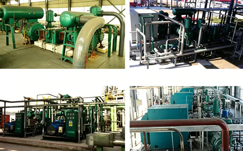
مطالعه موردی: ارتقاء بوستر نیتروژن کارخانه مایعسازی گاز
مشتری: یک مرکز فرآوری گاز کرایوژنیک در خاورمیانه که نیتروژن مایع را برای بازارهای صنعتی و پزشکی تولید میکند
چالش: بوستر نیتروژن روغنکاریشده موجود در این تأسیسات (برند آمریکایی، ۲۰ سال سابقه کار) در حال انتقال تدریجی روغن به جریان نیتروژن پرفشار تغذیهکننده چرخه مایعسازی بود. آلودگی روغن در مبدل حرارتی اصلی در حال یخ زدن بود و باعث انسدادهایی میشد که نیاز به خاموشیهای ماهانه برای یخزدایی و تمیزکاری داشت. هر خاموشی برنامهریزی نشده ۱.۴ لیتر در ساعت هزینه از دست دادن تولید داشت و تیم تعمیر و نگهداری ۳۰.۱ لیتر در ساعت از وقت خود را صرف مسائل مربوط به روغن میکرد. این تأسیسات به یک جایگزین بدون روغن قابل اعتماد نیاز داشت که قادر به ارائه بیش از ۳۰ متر مکعب در دقیقه با فشار ۳.۰۰ مگاپاسکال باشد.
راه حل: ما عرضه کردیم کمپرسور نیتروژن بدون روغن LW-33/30 به عنوان یک جایگزین مستقیم، بر روی یک اسکید سفارشی با اینترکولر یکپارچه، افترکولر و یک پنل کنترل PLC زیمنس S7-1200 با ادغام کامل SCADA پیکربندی شده است. مساحت اسکید به گونهای مهندسی شده است که با فونداسیون موجود مطابقت داشته باشد و اصلاحات عمرانی را حذف کند. طراحی سه ردیفه در مقایسه با کمپرسور تک ردیفه جایگزین شده، ویژگیهای ارتعاشی بهتری را ارائه میدهد و تنش فونداسیون را کاهش میدهد. یک مخزن سرج ۵ متر مکعبی در بالادست نصب شده است تا نوسانات فشار ناشی از ژنراتور نیتروژن بالادست را کاهش دهد.
نتایج کمی پس از ۲۴ ماه:
- میزان نیتروژن روغن: از ۲.۸ میلیگرم بر متر مکعب به کمتر از ۰.۰۱ میلیگرم بر متر مکعب کاهش یافت، دستیابی به استاندارد ISO 8573-1 کلاس 0
- گرفتگی مبدل حرارتی: کاملاً حذف شدبدون نیاز به خاموشی برای یخزدایی
- خرابیهای برنامهریزی نشده: از ۱۲ روز در سال به ۰ روز کاهش یافت، صرفه جویی ۱TP4T540,000 در تولید از دست رفته
- نیروی کار تعمیر و نگهداری: کاهش یافته توسط 35% زیرا تعمیر و نگهداری مربوط به روغن حذف شد
- مصرف انرژی: بهبود یافته توسط 8.2% در مقایسه با واحد جایگزین شده، صرفهجویی ۱TP4T28,000 در سال
- دوره بازگشت سرمایه: ۱.۴ سال تنها بر اساس کاهش زمان از کارافتادگی و صرفهجویی در هزینههای نگهداری
«LW-33/30 قابلیت اطمینان کارخانه مایعسازی ما را متحول کرده است. پیش از این، ما هر ماه با آلودگی روغن مبارزه میکردیم. اکنون، دو سال است که به مبدل حرارتی دست نزدهایم. طراحی بدون روغن، تنها با جلوگیری از خرابی، بارها هزینه خود را جبران کرده است.» — مدیر عملیات، تأسیسات فرآوری گاز کرایوژنیک
سوالات متداول و راهنمای انتخاب
محصولات و راهکارهای مرتبط
کمپرسورهای نیتروژن فشار بالای سری DW
سری DW که برای فشارهای تخلیه از 0.40 مگاپاسکال تا 2.00 مگاپاسکال طراحی شده است، تزریق نیتروژن، تقویت خط لوله فشار بالا و سنتز شیمیایی را پوشش میدهد. ظرفیتها از 2 تا 130 متر مکعب در دقیقه.
کمپرسورهای بدون روغن چند مرحلهای سری ZW
کمپرسورهای عمودی چند مرحلهای بدون روغن برای اکسیژن، نیتروژن، هیدروژن و گازهای تخصصی. فشارهای تخلیه تا 9.00 مگاپاسکال برای پر کردن گاز با فشار فوق العاده بالا و کاربردهای فرآیندهای شیمیایی.
کمپرسورهای نیتروژن با ظرفیت بالا سری LW
کمپرسورهای پیستونی بدون روغن با جریان بالا (20 تا 130 متر مکعب در دقیقه) برای پشتیبان گیری از واحد هوای فشرده برودتی، تقویت VPSA و توزیع خطوط لوله صنعتی. فشار تخلیه از 0.30 تا 0.80 مگاپاسکال.
برای یک مرور کلی جامع از ما کمپرسور نیتروژن صنعتی برای اطلاع از نمونه کارهای ما، شامل کمپرسورهای اکسیژن بدون روغن، کمپرسورهای هیدروژن، کمپرسورهای دی اکسید کربن و راهکارهای تخصصی گازسوز سفارشی، لطفاً با تیم مهندسی کاربردی ما تماس بگیرید یا کاتالوگ محصولات آنلاین ما را مرور کنید.
آماده ارتقاء سیستم نیتروژن فوق فشار بالای خود هستید؟
مهندسان ما آمادهاند تا نیازهای جریان نیتروژن، شرایط مکش، اهداف فشار تخلیه و محدودیتهای یکپارچهسازی شما را ارزیابی کنند. ما ظرف ۴۸ ساعت پس از دریافت درخواست شما، پیشنهادهای فنی رایگان، نقشههای چیدمان فونداسیون، نمودارهای لولهکشی و ابزار دقیق (P&ID) و تجزیه و تحلیل دقیق هزینه کل مالکیت (TCO) را ارائه میدهیم.
ایمیل: [email protected] | پاسخ ظرف ۲۴ ساعت