Beschrijving
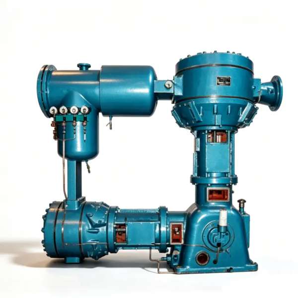
LW-60/8 stikstofcompressor – Olievrije N2-booster met ultrahoge capaciteit voor veeleisende industriële netwerken van 0,80 MPa
De LW-60/8 is een tweetraps, tweerijige olievrije zuigercompressor voor stikstof, ontworpen om 60 m³/min te leveren bij een persdruk van 0,80 MPa. Deze compressor is speciaal ontwikkeld voor grootschalige cryogene luchtscheiding, hogedruk VPSA-boosterstations en intensieve distributie via pijpleidingen voor petrochemische producten. De compressor is vrij van smeermiddelverontreiniging, geschikt voor continu gebruik en geoptimaliseerd voor onafgebroken industrieel gebruik, 24 uur per dag, 7 dagen per week, onder verhoogde druk.
Productoverzicht
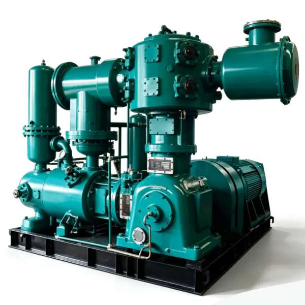
De LW-60/8 stikstofcompressor Dit product vertegenwoordigt het summum van ons portfolio van olievrije zuigercompressoren, ontworpen om te voldoen aan de meest veeleisende stikstofboostingseisen in grootschalige industriële gasinfrastructuur. Met een uitzonderlijke Capaciteit van 60 m³/min in combinatie met een robuuste 0,80 MPa uitlaatdrukDeze unit is de spil van grootschalige cryogene luchtseparatie-installaties, hogedruk VPSA-boosterstations en intensieve petrochemische distributienetwerken waar zowel debiet als druk van essentieel belang zijn.
Wat de LW-60/8 onderscheidt van conventionele gesmeerde alternatieven is zijn van nature olievrij compressiepadDe zuigerveren en geleidebanden zijn vervaardigd uit gepatenteerde zelfsmurende PTFE-composietmaterialen die volledig zonder koolwaterstofsmeermiddelen werken. Deze ontwerpfilosofie zorgt ervoor dat de stikstofproductstroom absoluut vrij blijft van olieverontreiniging, waardoor een optimale werking wordt bereikt. ISO 8573-1 Klasse 0-certificering Zonder dat er achteraf zuiveringsapparatuur nodig is. Voor bedrijven in de voedingsmiddelenindustrie, farmaceutische productie, halfgeleiderfabricage en petrochemische verwerking, elimineert deze van nature olievrije eigenschap de investeringskosten, onderhoudslasten en het energieverbruik van oliefiltratiesystemen.
De compressorarchitectuur volgt een tweetraps, twee rijen (二列二级) Een configuratie die de aanzienlijke drukverhouding optimaal verdeelt over twee compressiecilinders. Deze gefaseerde aanpak is essentieel voor het beheersen van de thermische belasting die gepaard gaat met een persdruk van 0,80 MPa, terwijl de dimensionale integriteit van de PTFE-afdichtingselementen behouden blijft. Elke fase is voorzien van een onafhankelijke, zeer efficiënte tussenkoeler, waardoor de gastemperaturen binnen veilige bedrijfsgrenzen blijven, zelfs bij langdurig gebruik op maximaal vermogen. Het massieve gietijzeren frame en de dynamisch gebalanceerde gesmede stalen krukas zijn ontworpen voor een minimale levensduur van... 120.000 uur volgens standaard onderhoudsprotocollen.
Technische specificaties – LW-60/8
| Parameter | Waarde | Eenheid |
|---|---|---|
| Model | LW-60/8 | – |
| Patroon | Tweetraps, twee rijen (二列二级) | – |
| Capaciteit | 60 | m³/min |
| Afvoerdruk | 0.80 | MPa |
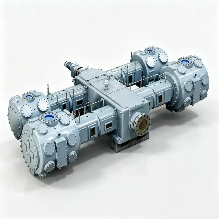
| Compressorafmetingen (L × B × H) | 2380 × 1500 × 2560 | mm |
| Gewicht | 6.50 | T |
| Stroom | 350 | kW |
| Spanning | 6k of 10k | V |
| Gasmedium | Stikstof (N₂) | – |
| Smering | Olievrij | – |
* Alle specificaties zijn gebaseerd op standaard referentieomstandigheden (ISO 1217, bijlage C). De werkelijke prestaties kunnen variëren afhankelijk van de hoogte van de locatie, de omgevingstemperatuur en de inlaatcondities.
Belangrijkste kenmerken en technische voordelen
1. Hittebestendige PTFE-composietafdichtingstechnologie
De LW-60/8 maakt gebruik van een geavanceerde technologie. zelfsmurende zuigerveer- en geleidebandassemblage Vervaardigd uit gepatenteerde PTFE-composieten versterkt met glasvezel, koolstofgrafiet en bronsdeeltjes. Deze materiaalsamenstelling bereikt een wrijvingscoëfficiënt van minder dan 0,06 zonder externe koolwaterstofsmering, waardoor het meevoeren van oliedampen in de stikstofproductstroom volledig wordt geëlimineerd. De ringen zijn specifiek ontworpen voor de verhoogde persgastemperaturen die gepaard gaan met een druk van 0,80 MPa, waarbij de dimensionale stabiliteit en afdichtingseffectiviteit behouden blijven tot 185 °C. Voor industriële gasbedrijven biedt dit de volgende voordelen: native ISO 8573-1 Klasse 0-conformiteit zonder de investeringskosten, de complexiteit van het onderhoud of het energieverbruik van de daaropvolgende oliefiltratieapparatuur.
2. Geavanceerde tweetraps thermodynamische optimalisatie
De tweetraps compressiearchitectuur De LW-60/8 is thermodynamisch geoptimaliseerd voor de veeleisende persdruk van 0,80 MPa. Door de aanzienlijke totale drukverhouding te verdelen over een lagedrukcilinder en een hogedrukcilinder, bereikt de compressor een aanzienlijk lagere gemiddelde effectieve temperatuur per trap in vergelijking met eentrapsontwerpen. Een speciaal ontworpen, zeer efficiënte buizenwarmtewisselaar tussen de trappen voert de compressiewarmte af, waardoor de perstemperatuur onder de 160 °C blijft, zelfs bij maximale continue belasting. Dit thermisch beheer is cruciaal voor het behoud van de integriteit van de PTFE-ringen en verlengt de levensduur van de klepplaten met ongeveer 451 TP3T ten opzichte van eentrapsalternatieven die werken bij equivalente drukverhoudingen.
3. Massief gietijzeren frame met superieure krachtbalans
Het hoofdframe is gegoten uit GG25 grijs gietijzer (gelijkwaardig aan ASTM A48 Klasse 30B) met geïntegreerde koelwaterkanalen die direct in het gietstuk zijn gefreesd. tweerijige opstelling van tegenover elkaar geplaatste cilinders Het systeem zorgt voor een natuurlijke, eerstegraads krachtcompensatie, waardoor de onbalans in de traagheidskrachten die op de fundering worden overgebracht met meer dan 851 TP3T wordt verminderd in vergelijking met enkelrijige ontwerpen met een gelijkwaardige capaciteit. Dit mechanische voordeel maakt installatie mogelijk op een gewapend betonnen traagheidsblok van minimaal 12 ton (versus 18+ ton voor enkelrijige equivalenten), wat de civieltechnische kosten aanzienlijk verlaagt en retrofit-installaties in bestaande compressorhuizen vereenvoudigt, waar de funderingscapaciteit mogelijk beperkt is.
4. Middenspanningsmotoraandrijving voor grootschalige integratie
De LW-60/8 wordt aangedreven door een 350 kW middenspanningsinductiemotor Verkrijgbaar in 6kV- of 10kV-uitvoeringen, conform IEC 60034-1 efficiëntieklasse IE3. De middenspanningsaandrijving maakt de noodzaak voor overgedimensioneerde laagspanningsschakelaars en onpraktisch dikke bekabeling, die nodig zouden zijn voor een 380V-motor met dit vermogen, overbodig. Directe integratie in industriële middenspanningsdistributienetwerken verlaagt de kosten van de elektrische infrastructuur, minimaliseert I²R-verliezen in de stroombekabeling en verbetert de algehele energie-efficiëntie. Voor installaties met 6kV- of 10kV-bussystemen, standaard in grote industriële complexen, biedt de LW-60/8 naadloze elektrische compatibiliteit.
Toepassingsscenario's
Mega-schaal cryogene luchtseparatie-installaties
In grootschalige cryogene ASU-installaties die 3.000–8.000 Nm³/u gasvormige stikstof produceren, dient de LW-60/8 als de primaire stikstofbooster met hoge capaciteit Tussen de koelbox en de verdeelleiding. De capaciteit van 60 m³/min komt overeen met de output van de grootste ASU's met één productielijn, terwijl de persdruk van 0,80 MPa voldoende opvoerhoogte biedt voor distributie via pijpleidingen over lange afstanden naar afnemers zoals geïntegreerde staalcomplexen, petrochemische krakers en LNG-liquefactie-installaties. Het olievrije ontwerp is absoluut cruciaal in deze toepassingen, omdat elke olieverontreiniging de zuiverheid van de stikstof zou aantasten die wordt geleverd aan de meest gevoelige processen, waaronder de fabricage van halfgeleiderwafels en aseptische vullijnen voor farmaceutische producten die door hetzelfde distributienetwerk worden bediend.
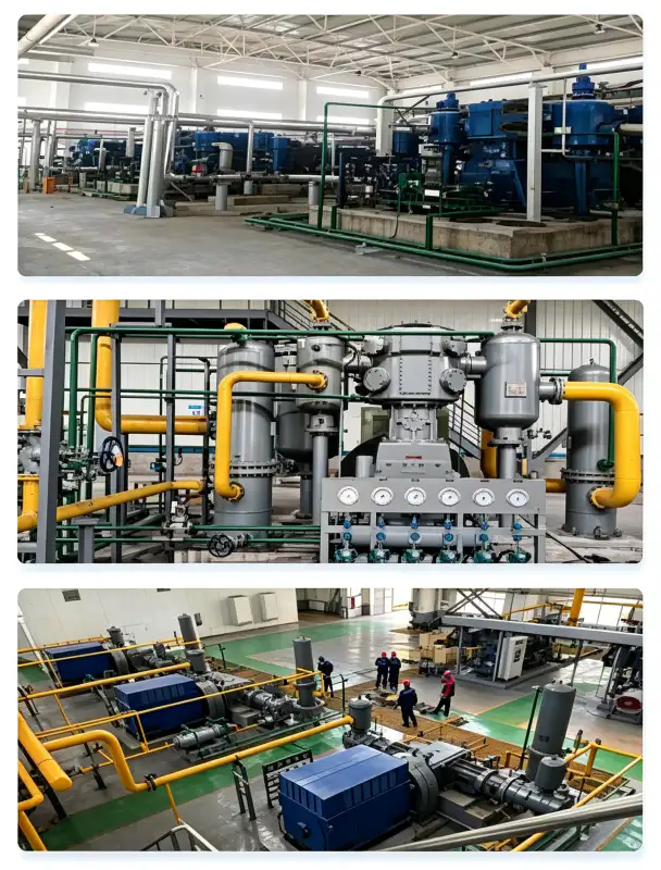
Hogedruk VPSA-stikstofboosterstations
Voor grote VPSA-stikstofgeneratoren die stikstof met een zuiverheid van 99,5–99,9% produceren bij een druk die dicht bij de atmosferische druk ligt, geldt het volgende: LW-60/8 stikstofbooster Het lagedrukproduct wordt gecomprimeerd tot 0,80 MPa voor distributie onder hoge druk. De verhoogde persdruk is met name waardevol voor VPSA-installaties die grote industrieterreinen of meerdere vestigingen bedienen via een gecentraliseerde hogedrukleiding, waar de drukverliezen in het distributienetwerk aanzienlijk kunnen zijn. Een olievrij compressiepad is essentieel voor VPSA-toepassingen, omdat koolwaterstofverontreiniging het koolstofmoleculaire zeefadsorbent onomkeerbaar zou aantasten, waardoor de scheidingsefficiëntie permanent zou afnemen en een kostbare volledige vervanging van het adsorbent noodzakelijk zou zijn.
Intensieve petrochemische hogedrukstikstofsystemen
In grote petrochemische complexen en raffinaderijen levert de LW-60/8 stikstof onder hoge druk voor reactor inertiseren, katalysator conserveren, pijpleiding doorspoelen, noodinjectie in het reservoir en vulling voor de hydrotest.De persdruk van 0,80 MPa is voldoende om de drukwaarden van de grootste procesvaten en reactorsystemen te overwinnen, waardoor directe stikstofinjectie mogelijk is zonder tussenliggende boostfasen. De classificatie voor continu bedrijf garandeert een ononderbroken beschikbaarheid van stikstof tijdens langdurige onderhoudsbeurten die meerdere weken kunnen duren. De olievrije certificering is verplicht voor petrochemische toepassingen waarbij stikstof in contact komt met katalysatorbedden of in processtromen terechtkomt die volledig koolwaterstofvrij moeten blijven.
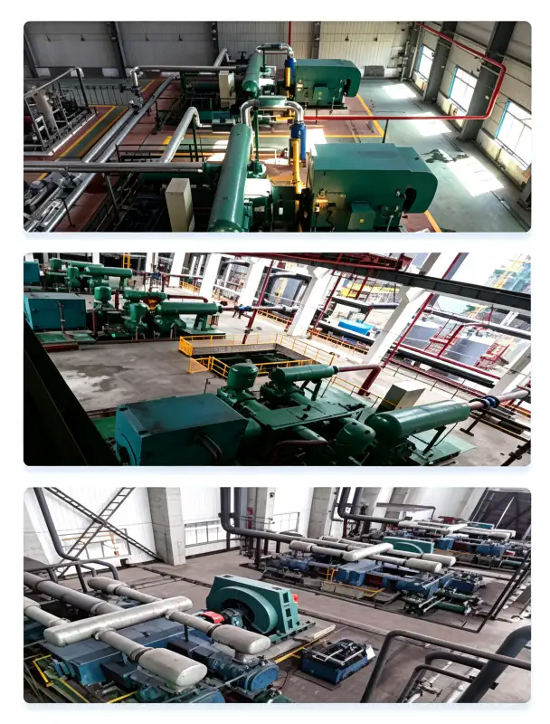
Geïntegreerde hogedruk-inertisering in staalfabrieken
Grote, geïntegreerde staalfabrieken met meerdere hoogovens, basiszuurstofovens en continugietlijnen hebben enorme hoeveelheden stikstof nodig voor Gasafdichting in hoogovens, inertisering van verdeelbakken, gietpanmetallurgie en gaszuivering in cokesovensDe LW-60/8 heeft een capaciteit van 60 m³/min en kan via een centrale hogedruk-stikstofleiding meerdere hoogovens of een compleet gieterijcomplex tegelijk bedienen. De persdruk van 0,80 MPa zorgt voor voldoende opvoerhoogte om de tegendruk van de grootste hoogovengassystemen te overwinnen en een positieve afdichtingsgasstroom op alle tuyèreniveaus te handhaven. Het olievrije ontwerp voorkomt olieverontreiniging van het hoogovengas, wat de gasreinigingsapparatuur stroomafwaarts zou vervuilen en de kwaliteit van het teruggewonnen hoogovengas voor energieopwekking en verwarming zou aantasten.
Materiaal en constructie
De LW-60/8 is vervaardigd uit hoogwaardige materialen die geselecteerd zijn op hun compatibiliteit met stikstof, geschiktheid voor hoge druk en een lange levensduur onder ve veeleisende omstandigheden.
| component | Materiaal | Specificatie |
|---|---|---|
| Cilinderblok | Grijs gietijzer | GG25 / HT250, geïntegreerde koelwatermantels |
| Krukas | Gesmeed gelegeerd staal | 42CrMo4, Q&T, ISO 1940 G2.5 dynamisch gebalanceerd |
| Zuigerveren | PTFE-glas-koolstof-bronscomposiet | Zelfsmerend, bestand tegen hoge temperaturen tot 185 °C. |
| Rider Bands | PTFE-composiet | Zuigergeleiding, anti-slijtage, slijtagesnelheid <0,035 mm/1000 uur |
| Klepplaten | Roestvrij staal | SS316, concentrisch ringvormig veerbelast ontwerp |
| Drijfstangen | Gesmeed staal met Babbitt-lagers | Nauwkeurig bewerkte, oliegesmeerde drijfstanglager |
| Intercooler | Behuizing van koolstofstaal / buizen van RVS 316 | ASME VIII Div.1, 1,5× hydrotest, 30 min vasthouden |
| Nakoeler | Behuizing van koolstofstaal / buizen van RVS 316 | Hoogrendements koelbuis met vinnen, koelwater van 32 °C. |
| Basisframe | Constructiestaal | Gelaste constructie, trillingsdempende montageplaten |
Alle drukdragende componenten worden ontworpen en vervaardigd in strikte overeenstemming met ASME BPVC Sectie VIII Divisie 1 of de Chinese GB 150-normen. Elke lasverbinding ondergaat een 100%-radiografische inspectie (RT) volgens ASME Sectie V, Artikel 2, en elk voltooid drukvat wordt onderworpen aan een hydrostatische druktest bij 1,5 keer de maximaal toelaatbare werkdruk (MAWP) gedurende een minimale wachttijd van 30 minuten.
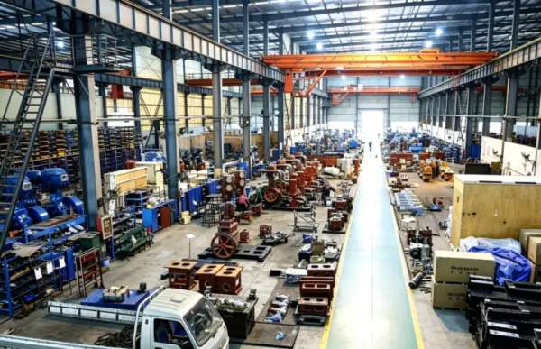
Installatie- en onderhoudsrichtlijnen
Fundament- en constructie-eisen
De LW-60/8 heeft een droog gewicht van 6,50 ton en een zwaartepunt op circa 950 mm boven de grondplaat. Dankzij het ontwerp met twee rijen tegenover elkaar geplaatste cilinders zijn de onbalanskrachten minimaal, waardoor installatie op een gewapend betonnen traagheidsblok van 12-14 tonHet blok moet op elastomere trillingsdempers (eigen frequentie 6–8 Hz) worden gemonteerd om trillingsoverdracht naar aangrenzende constructies en gevoelige instrumentatie te voorkomen. Minimale vrije ruimte: 1,5 m aan de niet-aandrijfzijde voor toegang tot de klep, 1,2 m aan de aandrijfzijde voor motoronderhoud en 2,0 m boven het hoofd voor toegang met een kraan tijdens grote revisies.
Ontwerp van koelwatersystemen
De koelwaterbehoefte bedraagt ongeveer 60 m³/h bij een inlaattemperatuur van maximaal 32 °C. Het waterdistributiecircuit voorziet de cilindermantels, de tussenkoeler en de nakoeler van water via parallelle aftakkingen. Specificaties voor de waterkwaliteit: pH 6,5–8,5, totaal opgeloste stoffen < 500 mg/L, chloridegehalte < 50 mg/L (om corrosie van de SS316-buizen in de koelers te voorkomen), zwevende deeltjes < 30 mg/L en totale hardheid < 300 mg/L als CaCO₃. Voor locaties met een marginale waterkwaliteit wordt een gesloten koeltoren met zijstroomfiltratie en chemische behandeling sterk aanbevolen om kalkaanslag en corrosie te voorkomen.
Preventief onderhoudsschema
| Interval | Serviceartikel | Actie vereist |
|---|---|---|
| Dagelijks | Operationele inspectie | Controleer trillingsniveaus, abnormale geluiden, koelwaterdebiet en uitlaattemperatuur. |
| 250 uur | Klepplaatinspectie | Verwijder en inspecteer de zuig-/perskleppen op koolstofafzettingen, veervermoeidheid of scheuren. |
| 1.000 uur | Beoordeling van de slijtage van de zuigerveren | Meet de speling in de groef van de zuigerveren; vervang de zuigerveren als de speling groter is dan 0,22 mm. |
| 4000 uur | Tussentijdse revisie | Vervang alle zuigerveren, geleidebanden en klepplaatassemblages. |
| 8.000 uur | Grote revisie | Controleer de krukaslagertappen, meet de speling van de hoofdlagers en vervang de lagers indien deze groter is dan 0,08 mm. |
Het olievrije ontwerp van de LW-60/8 vermindert de onderhoudscomplexiteit aanzienlijk in vergelijking met gesmeerde alternatieven. Er hoeven geen olieverversingen te worden ingepland, geen smeeroliemonsters te worden geanalyseerd, geen oliefilterelementen te worden vervangen en geen olieafscheiderpatronen te worden gecontroleerd. De belangrijkste slijtageonderdelen zijn de PTFE-zuigerveren en geleidebandendie doorgaans een levensduur van 4.000 tot 6.000 bedrijfsuren halen onder schone stikstofomstandigheden. Deze vereenvoudiging van het onderhoud vertaalt zich in lagere arbeidskosten, een kleinere voorraad reserveonderdelen en een hogere beschikbaarheid van de apparatuur.

Certificeringen voor naleving en veiligheid
De LW-60/8 stikstofcompressor is ontworpen, gefabriceerd en getest om te voldoen aan, of te overtreffen, de volgende internationale normen en wettelijke kaders:
ASME BPVC Sectie VIII Div.1, GB 150-2011, PED 2014/68/EU Module A
IEC 60034-1 (IE3-efficiëntie), IEC 60204-1, ISO 12100 machineveiligheid
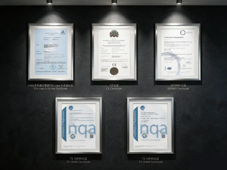
ISO 8573-1 Klasse 0 (oliegehalte), onafhankelijk getest door TÜV Rheinland
ISO 9001:2015 (Kwaliteitsmanagement), ISO 14001:2015 (Milieumanagement)
Stikstof wordt geclassificeerd als een eenvoudig verstikkend gas. Alle LW-60/8-installaties moeten continue zuurstoftekortmonitoring omvatten in de compressorruimte en alle aangrenzende ruimten waar stikstoflekkage zich kan ophopen. Ventilatiesystemen moeten zodanig zijn ontworpen dat de omgevingszuurstofconcentratie boven 19,5 l/3 ton volume blijft, conform OSHA 29 CFR 1910.146 (Besloten ruimten waarvoor een vergunning vereist is). Noodstopsystemen moeten activeren bij 19,5 l/3 ton O₂ (alarm) en de compressor automatisch uitschakelen bij 18,0 l/3 ton O₂ (harde uitschakeling). Toegangsprocedures voor personeel tot afgesloten compressorruimten moeten draagbare zuurstofmonitoren en een buddy-systeemprotocol omvatten.
Prestatie- en efficiëntieanalyse
De LW-60/8 behaalt een specifiek energieverbruik van circa 5,83 kW per m³/min stikstof wordt geleverd bij een persdruk van 0,80 MPa. Deze efficiëntie is concurrerend voor een olievrije zuigercompressor met ultrahoge capaciteit die werkt bij een verhoogde drukverhouding, waardoor de unit gunstig gepositioneerd is binnen de capaciteitsklasse van 50-70 m³/min. Ter vergelijking: oliegesmeerde schroefcompressoren in vergelijkbare hogedruktoepassingen verbruiken doorgaans 6,2-7,0 kW/m³/min, terwijl traditionele eentraps zuigercompressoren bij equivalente persdrukken meer dan 8,0 kW/m³/min kunnen verbruiken.
Bij een standaard jaarlijks bedrijfsschema van 8.000 uur levert het efficiëntievoordeel van de LW-60/8 een besparing op van circa 180.000–420.000 kWh aan jaarlijkse energiebesparing vergeleken met minder efficiënte alternatieven. Bij een gemiddeld industrieel elektriciteitstarief van $0,08/kWh vertegenwoordigt dit een directe besparing op de bedrijfskosten per jaar van $14.400–$33.600. In combinatie met de volledige eliminatie van oliegerelateerde verbruiksartikelen (smeerolie, filterelementen, separatorpatronen, afvalolieverwerking en olieanalyse), totale eigendomskosten voor stikstofcompressie wordt naar schatting met 22–32% verminderd gedurende een operationele levensduur van 10 jaar.
De afwezigheid van olie in het compressietraject elimineert ook het energieverlies dat gepaard gaat met de olieverwijderingsapparatuur stroomafwaarts. Een typische oliegesmeerde compressor van deze grootte en drukklasse vereist coalescentiefilters, actieve kooladsorbers en continue oliemonitoringsapparatuur die samen 3 tot 51 ton van het vermogen van de compressor verbruiken. Het olievrije ontwerp van de LW-60/8 elimineert deze parasitaire belasting volledig, waardoor de effectieve systeemefficiëntie verder wordt verbeterd.
Mogelijkheden voor maatwerk en OEM-productie
We bieden uitgebreide aanpassingsmogelijkheden om de LW-60/8 af te stemmen op specifieke locatieomstandigheden, integratievereisten en specificaties van de eindgebruiker:
- Kant-en-klare pakketten op een frame: De compressor, motor, tussenkoeler, nakoeler, instrumentatie en het bedieningspaneel zijn voorgemonteerd op een stalen frame met geïntegreerde hijsogen en ankerboutsjablonen. Deze aanpak verkort de installatietijd op locatie met ongeveer 60% en minimaliseert de risico's tijdens de inbedrijfstelling door alle systemen uitgebreid in de fabriek te testen.
- Configuraties van gevaarlijke zones: Motor- en elektrische behuizingen die voldoen aan de ATEX Zone 2- en IECEx-normen zijn beschikbaar voor installaties in petrochemische installaties waar incidenteel explosieve atmosferen kunnen voorkomen. Geïntegreerde gasdetectie en automatische ventilatievergrendelingen kunnen in het besturingssysteem worden opgenomen.
- Geavanceerde procesbesturing: Optioneel verkrijgbaar: Siemens S7-1200 of Allen-Bradley CompactLogix PLC met 10-inch HMI-touchscreen, bewaking op afstand via Modbus TCP/IP of OPC-UA, en naadloze integratie met DCS/SCADA-systemen van de fabriek. Automatische laad-/losregeling en compatibiliteit met frequentieomvormers (VFD's) optimaliseren de efficiëntie bij deellast en verminderen mechanische slijtage tijdens het opstarten.
- Milieubeschermingssystemen: C5-M coatingsystemen van maritieme kwaliteit voor installaties aan de kust of op zee; tropische elektrische componenten voor omgevingstemperaturen tot 55 °C; en IP54-gecertificeerde geluidsisolerende behuizingen die de geluidsemissie reduceren van 85 dB(A) tot 72 dB(A) op 1 meter afstand, geschikt voor binneninstallaties zonder aparte compressorruimte.
- OEM- en private labelprogramma's: Aangepaste lakkleuren, naamplaatjes met logo en lokale documentatiepakketten zijn beschikbaar voor distributeurs van gasapparatuur en systeemintegratoren. Technische handleidingen, onderdelenlijsten en onderhoudsprocedures kunnen in meerdere talen worden geleverd.
Aangepaste configuraties zijn beschikbaar via Minimale bestelhoeveelheid: 1 stukDe technische beoordeling en het opstellen van een voorstel duren doorgaans 5-7 werkdagen. De standaard levertijd is 12-14 weken; herhaalbestellingen worden binnen 8-10 weken na orderbevestiging geleverd.
Casestudie: Herziening van de stikstofdistributie in een petrochemisch complex
Cliënt: Een groot petrochemisch complex in het Midden-Oosten met drie ethyleenkrakers, twee polyethyleenfabrieken en een polypropyleeneenheid.
Uitdaging: De stikstofvoorziening van het complex werd verzorgd door drie verouderde, oliegesmeerde compressoren (twee Europese merken, één Aziatisch merk, 16-22 jaar in gebruik) die een gemeenschappelijke verdeelleiding van 0,60 MPa voedden. De compressoren vertoonden een toenemende olielekkage in de stikstofstroom, waardoor de katalysatorbedden in de ethyleenkrakers werden verontreinigd en polymerisatieproblemen in de polyethyleenreactoren ontstonden. De onderhoudskosten waren gestegen tot 1.400.120.000 euro per jaar, en de druk van 0,60 MPa was onvoldoende voor de nieuwe hogedruk-inertiseringseisen van de reactoren. Het complex had minimaal 55 m³/min bij 0,80 MPa nodig om aan de uitgebreide productiedoelstellingen te voldoen.
Oplossing: Wij leverden een LW-60/8 olievrije stikstofcompressor De nieuwe primaire compressor werd gemonteerd op een op maat gemaakt frame met geïntegreerde tussenkoeler, nakoeler en een Siemens S7-1200 PLC-besturingspaneel met volledige SCADA-integratie. De persdruk van 0,80 MPa voldeed aan alle nieuwe eisen voor hogedrukinertisering, terwijl het olievrije ontwerp verontreiniging van katalysatorbedden en polymerisatiereactoren voorkwam. Een buffervat van 10 m³ werd stroomopwaarts geïnstalleerd om vraagfluctuaties van de verschillende proceseenheden op te vangen. De twee bestaande compressoren werden behouden als reserve-eenheden.
Gekwantificeerde resultaten na 24 maanden:
- Stikstofgehalte van de olie: Verlaagd van 5,8 mg/m³ naar <0,01 mg/m³, waarbij de ISO 8573-1 Klasse 0-certificering is behaald.
- Vervangingsfrequentie van het katalysatorbed: Verlengd van 18 maanden naar 48 maanden.waardoor jaarlijks $180.000 aan katalysatorkosten wordt bespaard
- Verontreinigingsincidenten in de polymerisatiereactor: Volledig geëlimineerdwaardoor de productie conform de specificaties met 2,1% wordt verbeterd.
- Jaarlijkse onderhoudskosten: Verminderd met 48% ($120.000 tot $62.400) door het elimineren van oliegerelateerde reparaties
- Energieverbruik: Verbeterd door 8.2% ten opzichte van de primair vervangen unit, wat een besparing oplevert van ongeveer $24.800/jaar.
- Ongeplande downtime: Nul gebeurtenissen in 24 maanden ononderbroken bedrijf
“De LW-60/8 heeft onze stikstofbetrouwbaarheid volledig getransformeerd. Door de eliminatie van olieverontreiniging is de levensduur van onze katalysator met een factor 2,5 verlengd en zijn incidenten met reactorverontreiniging voorkomen. Ons onderhoudsteam kan nu worden ingezet voor preventieve taken in plaats van constante reparaties die verband houden met olie. De terugverdientijd bedroeg minder dan 16 maanden.” — Hoofd operationele zaken, petrochemisch complex
Veelgestelde vragen en selectiegids
Gerelateerde producten en oplossingen
LW-52/8 stikstofcompressor met hoge capaciteit
Een variant met een iets lagere capaciteit, die 52 m³/min levert bij 0,80 MPa, ideaal voor toepassingen waar de volledige 60 m³/min van de LW-60/8 niet nodig is. Biedt dezelfde olievrije technologie en technische normen.
DW-serie hogedruk stikstofcompressoren
De DW-serie is ontworpen voor persdrukken van 0,40 MPa tot 2,00 MPa en is geschikt voor stikstofinjectie, hogedrukverhoging in pijpleidingen en chemische synthese. Capaciteiten van 2 tot 130 m³/min.
ZW-serie meertraps olievrije compressoren
Verticale, meertraps olievrije compressoren voor zuurstof, stikstof, waterstof en speciale gassen. Persdrukken tot 9,00 MPa voor hogedrukgasvulling, cilindervulling en chemische procestoepassingen.
Voor een uitgebreid overzicht van onze industriële stikstofcompressor Voor ons portfolio, inclusief olievrije zuurstofcompressoren, waterstofcompressoren, koolstofdioxidecompressoren en op maat gemaakte oplossingen voor speciale gassen, kunt u contact opnemen met ons applicatieteam of onze online productcatalogus raadplegen.
Klaar om uw stikstofsysteem met ultrahoge capaciteit te transformeren?
Onze applicatie-ingenieurs staan klaar om uw stikstofdebietvereisten, zuigomstandigheden, streefwaarden voor de persdruk en integratiebeperkingen te evalueren. Wij leveren binnen 48 uur na ontvangst van uw aanvraag gratis technische voorstellen, funderingstekeningen, leiding- en instrumentatiediagrammen (P&ID's) en gedetailleerde analyses van de totale eigendomskosten (TCO).
E-mail: [email protected] | Reactie binnen 24 uur