
説明
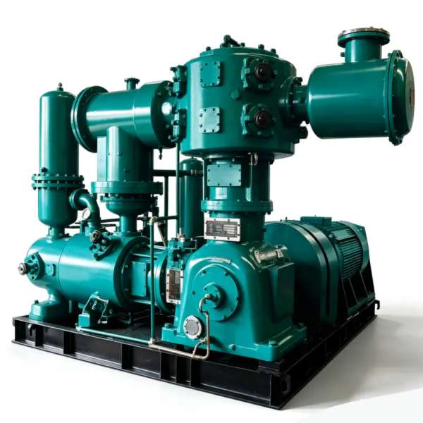
LW-60/8 窒素コンプレッサー – 要求の厳しい0.80 MPa産業ネットワーク向け超大容量オイルフリーN2ブースター
Engineered to deliver 60 m³/min at 0.80 MPa discharge pressure, the LW-60/8 is a two-stage, two-row oil-free piston nitrogen compressor purpose-built for mega-scale cryogenic air separation, high-pressure VPSA booster stations, and intensive petrochemical pipeline distribution. Zero lubricant contamination, continuous-duty rated, and optimized for relentless 24/7 industrial operation at elevated pressure.
製品概要
の LW-60/8 nitrogen compressor represents the pinnacle of our oil-free piston compressor portfolio, engineered to satisfy the most demanding nitrogen boosting requirements in large-scale industrial gas infrastructure. With an exceptional 60 m³/min capacity paired with a robust 0.80 MPa discharge pressure, this unit stands as the workhorse of mega-scale cryogenic air separation plants, high-pressure VPSA booster stations, and intensive petrochemical distribution networks where both flow and pressure are non-negotiable.
What distinguishes the LW-60/8 from conventional lubricated alternatives is its intrinsically oil-free compression pathway. The piston rings and rider bands are fabricated from proprietary self-lubricating PTFE composite materials that operate entirely without hydrocarbon lubricants. This design philosophy ensures the nitrogen product stream remains absolutely free of oil contamination, achieving ISO 8573-1 クラス0認証 without any downstream purification equipment. For operators in food processing, pharmaceutical manufacturing, semiconductor fabrication, and petrochemical processing, this native oil-free characteristic eliminates the capital expenditure, maintenance burden, and energy penalty of oil-filtration systems.
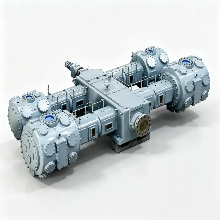
The compressor architecture follows a 二段二列 (二列二级) configuration that optimally distributes the substantial pressure ratio across two compression cylinders. This staged approach is essential for managing the thermal loads associated with 0.80 MPa discharge pressure while preserving the dimensional integrity of the PTFE sealing elements. Each stage incorporates an independent high-efficiency intercooler, ensuring gas temperatures remain within safe operating envelopes even during sustained maximum-capacity operation. The massive cast-iron frame and dynamically balanced forged steel crankshaft are rated for a minimum service life of 12万時間 標準的な保守手順に従って。
Technical Specifications – LW-60/8
| パラメータ | 価値 | ユニット |
|---|---|---|
| モデル | LW-60/8 | – |
| パターン | 二段二列 (二列二级) | – |
| 容量 | 60 | m³/分 |
| 吐出圧力 | 0.80 | MPa |
| コンプレッサーのサイズ(長さ×幅×高さ) | 2380 × 1500 × 2560 | mm |
| 重さ | 6.50 | t |
| 力 | 350 | kW |
| 電圧 | 6,000円または10,000円 | V |
| ガス媒体 | 窒素(N₂) | – |
| 潤滑 | オイルフリー | – |
* すべての仕様は標準基準条件(ISO 1217、附属書C)に基づいています。実際の性能は、設置場所の標高、周囲温度、および吸気条件によって異なる場合があります。
主な特長とエンジニアリング上の利点
1. High-Temperature PTFE Composite Sealing Technology
The LW-60/8 employs an advanced 自己潤滑ピストンリングおよびライダーバンドアセンブリ manufactured from proprietary PTFE composites reinforced with glass fiber, carbon graphite, and bronze particulates. This material formulation achieves a coefficient of friction below 0.06 without any external hydrocarbon lubrication, completely eliminating oil vapor carryover into the nitrogen product stream. The rings are specifically engineered for the elevated discharge temperatures associated with 0.80 MPa operation, maintaining dimensional stability and sealing effectiveness up to 185°C. For industrial gas operators, this delivers native ISO 8573-1 Class 0 compliance without the capital cost, maintenance complexity, or energy penalty of downstream oil-filtration equipment.
2. Advanced Two-Stage Thermodynamic Optimization
の 2段階圧縮アーキテクチャ of the LW-60/8 is thermodynamically optimized for the demanding 0.80 MPa discharge pressure target. By dividing the substantial overall pressure ratio between a low-pressure cylinder and a high-pressure cylinder, the compressor achieves a significantly lower mean effective temperature per stage compared to single-stage designs. A dedicated high-efficiency shell-and-tube intercooler between stages removes the heat of compression, maintaining discharge temperatures below 160°C even at maximum continuous load. This thermal management is critical for preserving PTFE ring integrity and extending valve plate service life by approximately 45% versus single-stage alternatives operating at equivalent pressure ratios.
3. Massive Cast-Iron Frame with Superior Force Balance
メインフレームは鋳造されています GG25 グレー鋳鉄 (equivalent to ASTM A48 Class 30B) with integral cooling water passages machined directly into the casting. The two-row opposed-cylinder arrangement provides natural first-order force cancellation, reducing the unbalanced inertia forces transmitted to the foundation by over 85% compared to single-row designs of equivalent capacity. This mechanical advantage permits installation on a reinforced concrete inertia block of minimum 12 tonnes (versus 18+ tonnes for single-row equivalents), significantly reducing civil engineering costs and simplifying retrofit installations in existing compressor houses where foundation capacity may be constrained.
4. Medium-Voltage Motor Drive for Large-Scale Integration
The LW-60/8 is driven by a 350 kW medium-voltage induction motor available in either 6kV or 10kV configurations, conforming to IEC 60034-1 efficiency class IE3. The medium-voltage drive eliminates the need for oversized low-voltage switchgear and impractically heavy-gauge cabling that would be required for a 380V motor of this power rating. Direct integration into industrial medium-voltage distribution networks reduces electrical infrastructure costs, minimizes I²R losses in power cabling, and improves overall energy efficiency. For facilities with 6kV or 10kV bus systems standard in large industrial plants, the LW-60/8 offers seamless electrical compatibility.
アプリケーションシナリオ
Mega-Scale Cryogenic Air Separation Plants
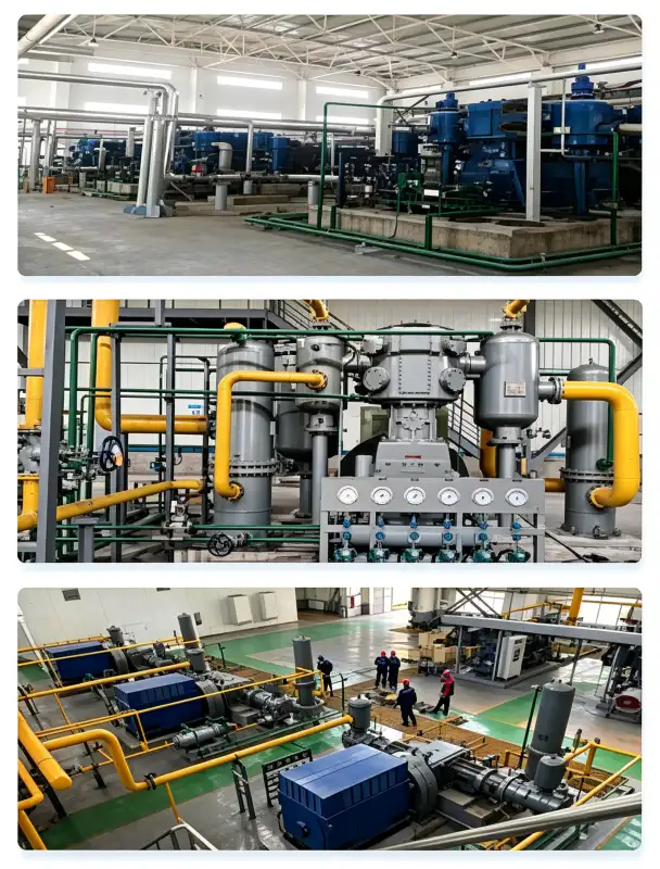
In mega-scale cryogenic ASU facilities producing 3,000–8,000 Nm³/h of gaseous nitrogen, the LW-60/8 serves as the primary high-capacity nitrogen booster between the cold box and the distribution header. Its 60 m³/min capacity matches the output of the largest single-train ASUs, while the 0.80 MPa discharge pressure provides ample head for long-distance pipeline distribution to downstream consumers such as integrated steel complexes, petrochemical crackers, and LNG liquefaction trains. The oil-free design is absolutely critical in these applications because any oil contamination would compromise the purity of nitrogen supplied to the most sensitive processes, including semiconductor wafer fabrication and pharmaceutical aseptic filling lines served by the same distribution network.
High-Pressure VPSA Nitrogen Booster Stations
For large VPSA nitrogen generators producing 99.5–99.9% purity nitrogen at near-atmospheric pressure, the LW-60/8 nitrogen booster compresses the low-pressure product to 0.80 MPa for high-pressure distribution. The elevated discharge pressure is particularly valuable for VPSA installations serving extensive industrial parks or multiple facilities through a centralized high-pressure header, where pressure losses across the distribution network can be substantial. The oil-free compression path is non-negotiable in VPSA service because hydrocarbon contamination would irreversibly poison the carbon molecular sieve adsorbent, permanently degrading separation efficiency and necessitating costly complete adsorbent replacement.
Intensive Petrochemical High-Pressure Nitrogen Systems
In large petrochemical complexes and refinery operations, the LW-60/8 provides high-pressure nitrogen for reactor inerting, catalyst preservation, pipeline purging, emergency vessel injection, and hydrotest filling. The 0.80 MPa discharge pressure is sufficient to overcome the pressure ratings of the largest process vessels and reactor systems, allowing direct nitrogen injection without intermediate boosting stages. The continuous-duty rating ensures uninterrupted nitrogen availability during extended turnaround campaigns that may span several weeks. The oil-free certification is mandatory for petrochemical applications where nitrogen contacts catalyst beds or enters process streams that must remain completely hydrocarbon-free.
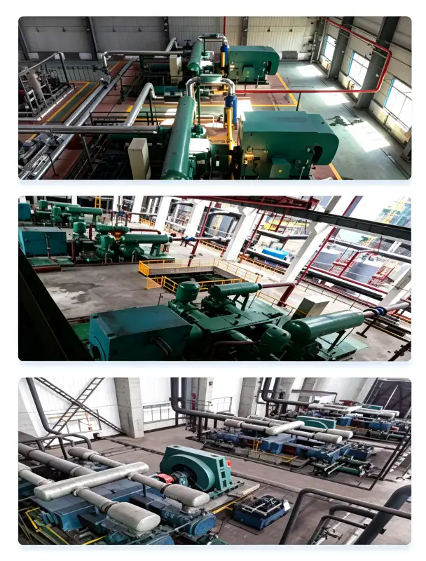
Integrated Steel Mill High-Pressure Inerting
Large integrated steel mills with multiple blast furnaces, basic oxygen furnaces, and continuous casting lines require enormous volumes of nitrogen for blast furnace gas sealing, tundish inerting, ladle metallurgy, and coke oven gas purging. The LW-60/8’s 60 m³/min capacity can serve multiple blast furnaces or an entire casting complex simultaneously through a centralized high-pressure nitrogen header. The 0.80 MPa discharge pressure provides adequate head to overcome the back-pressure of the largest blast furnace gas systems and maintain positive sealing gas flow at all tuyere levels. The oil-free design prevents oil contamination of blast furnace gas, which would foul downstream gas cleaning equipment and compromise the quality of recovered blast furnace gas used for power generation and heating.
材料と構造
The LW-60/8 is constructed from premium materials selected for nitrogen compatibility, high-pressure service, and extended operational life under demanding conditions:
| 成分 | 材料 | 仕様 |
|---|---|---|
| シリンダーブロック | ねずみ鋳鉄 | GG25 / HT250, integral cooling water jackets |
| クランクシャフト | 鍛造合金鋼 | 42CrMo4, Q&T, ISO 1940 G2.5 dynamically balanced |
| ピストンリング | PTFE-Glass-Carbon-Bronze Composite | Self-lubricating, high-temp rated to 185°C |
| ライダーバンド | PTFE複合材 | Piston guidance, anti-scuffing, wear rate <0.035 mm/1000h |
| バルブプレート | ステンレス鋼 | SS316、同心円状のバネ式設計 |
| コネクティングロッド | 鍛造鋼製、バビットメタルベアリング使用 | 精密加工されたオイル潤滑式ビッグエンド |
| インタークーラー | 炭素鋼製シェル/SS316製チューブ | ASME VIII Div.1、1.5倍の耐圧試験、30分間保持 |
| アフタークーラー | 炭素鋼製シェル/SS316製チューブ | High-efficiency finned tube, 32°C cooling water |
| ベースフレーム | Structural Steel | Welded fabrication, vibration-damped mounting pads |
すべての圧力支持部品は、以下の基準に厳密に従って設計および製造されています。 ASME BPVC セクション VIII ディビジョン 1 or Chinese GB 150 standards. Every weld joint undergoes 100% radiographic inspection (RT) per ASME Section V, Article 2, and each completed pressure vessel is subjected to a hydrostatic pressure test at 1.5 times the maximum allowable working pressure (MAWP) for a minimum hold period of 30 minutes.
設置およびメンテナンスに関するガイドライン
基礎および構造要件
The LW-60/8 has a dry weight of 6.50 tonnes and a center of gravity approximately 950 mm above the baseplate. Thanks to the two-row opposed-cylinder design, unbalanced forces are minimal, permitting installation on a reinforced concrete inertia block of 12–14 tonnes. The block should be mounted on elastomeric vibration isolators (natural frequency 6–8 Hz) to prevent vibration transmission to adjacent structures and sensitive instrumentation. Minimum clearance requirements: 1.5 m on the non-drive side for valve access, 1.2 m on the drive side for motor maintenance, and 2.0 m overhead for crane access during major overhauls.
冷却水システムの設計
冷却水の需要は約 60 m³/h at an inlet temperature not exceeding 32°C. The water distribution circuit supplies the cylinder jackets, intercooler, and aftercooler in parallel branches. Water quality specifications: pH 6.5–8.5, total dissolved solids < 500 mg/L, chloride content < 50 mg/L (to prevent SS316 tube corrosion in the coolers), suspended solids < 30 mg/L, and total hardness < 300 mg/L as CaCO₃. For sites with marginal water quality, a closed-loop cooling tower with side-stream filtration and chemical treatment is strongly recommended to prevent scale formation and corrosion.
予防保守スケジュール
| 間隔 | サービス項目 | 対応が必要 |
|---|---|---|
| 毎日 | 運用検査 | 振動レベル、異常な騒音、冷却水流量、吐出温度を確認してください。 |
| 250時間 | バルブプレートの点検 | Remove and inspect suction/discharge valves for carbon deposits, spring fatigue, or cracking |
| 1,000時間 | ピストンリング摩耗評価 | Measure ring groove clearance; replace rings if clearance exceeds 0.22 mm |
| 4,000時間 | 中間オーバーホール | ピストンリング、ライダーバンド、バルブプレートアセンブリをすべて交換してください。 |
| 8,000時間 | 大規模な改修 | Inspect crankshaft journals, measure main bearing clearances, replace bearings if >0.08 mm |
The oil-free design of the LW-60/8 dramatically reduces maintenance complexity compared to lubricated alternatives. There are no oil changes to schedule, no lubricating oil samples to analyze, no oil filter elements to replace, and no oil separator cartridges to monitor. The primary consumable wear items are the PTFE製ピストンリングおよびライダーバンド, which typically achieve 4,000–6,000 hours of service life under clean nitrogen conditions. This maintenance simplification translates to lower labor costs, reduced spare parts inventory, and higher equipment availability.

法令遵守および安全認証
The LW-60/8 nitrogen compressor is designed, manufactured, and tested to meet or exceed the following international standards and regulatory frameworks:
ASME BPVC セクション VIII Div.1、GB 150-2011、PED 2014/68/EU モジュール A
IEC 60034-1(IE3効率)、IEC 60204-1、ISO 12100機械安全規格
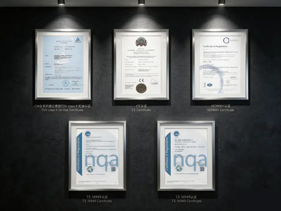
ISO 8573-1 クラス0(油分含有量)、TÜVラインランドによる独立試験済み
ISO 9001:2015(品質マネジメント)、ISO 14001:2015(環境マネジメント)
Nitrogen is classified as a simple asphyxiant gas. All LW-60/8 installations must incorporate continuous oxygen deficiency monitoring in the compressor room and all adjacent areas where nitrogen leakage could accumulate. Ventilation systems must be engineered to maintain ambient oxygen concentrations above 19.5% volume per OSHA 29 CFR 1910.146 (Permit-Required Confined Spaces). Emergency shutdown interlocks should activate at 19.5% O₂ (alarm) and trigger automatic compressor isolation at 18.0% O₂ (hard shutdown). Personnel entry procedures into enclosed compressor rooms must include portable oxygen monitors and a buddy-system protocol.
パフォーマンスと効率の分析
The LW-60/8 achieves a specific power consumption of approximately 5.83 kW per m³/min of nitrogen delivered at 0.80 MPa discharge pressure. This efficiency metric is competitive for an ultra-high-capacity oil-free piston compressor operating at an elevated pressure ratio, positioning the unit favorably within the 50–70 m³/min capacity class. For comparison, oil-lubricated screw compressors in similar high-pressure applications typically consume 6.2–7.0 kW/m³/min, while legacy single-stage piston designs may exceed 8.0 kW/m³/min at equivalent discharge pressures.
Over a standard 8,000-hour annual operating schedule, the LW-60/8’s efficiency advantage generates approximately 180,000–420,000 kWh of annual energy savings compared to less efficient alternatives. At an average industrial electricity tariff of $0.08/kWh, this represents $14,400–$33,600 in direct operating cost reduction per year. When combined with the complete elimination of oil-related consumables (lubricating oil, filter elements, separator cartridges, waste oil disposal, and oil analysis), the 窒素圧縮の総所有コスト is reduced by an estimated 22–32% over a 10-year operational life.
The absence of oil in the compression path also eliminates the energy penalty associated with downstream oil-removal equipment. A typical oil-lubricated compressor of this size and pressure rating requires coalescing filters, activated carbon adsorbers, and continuous oil monitoring instrumentation that collectively consume 3–5% of the compressor’s power output. The LW-60/8’s oil-free design removes this parasitic load entirely, further improving effective system efficiency.
カスタマイズおよびOEM対応
We offer extensive customization options to adapt the LW-60/8 to specific site conditions, integration requirements, and end-user specifications:
- スキッドマウント型ターンキーパッケージ: The compressor, motor, intercooler, aftercooler, instrumentation, and control panel are pre-assembled on a structural steel skid with integrated lifting lugs and anchor bolt templates. This approach reduces field installation time by approximately 60% and minimizes commissioning risks through comprehensive factory pre-testing of all systems.
- 危険区域構成: ATEX Zone 2 and IECEx compliant motor and electrical enclosures are available for installations in petrochemical facilities where explosive atmospheres may occasionally be present. Integrated gas detection and automatic ventilation interlocks can be incorporated into the control system.
- 高度なプロセス制御: Optional Siemens S7-1200 or Allen-Bradley CompactLogix PLC with 10-inch HMI touchscreen, remote monitoring via Modbus TCP/IP or OPC-UA, and seamless integration with plant DCS/SCADA systems. Automatic load/unload control and variable frequency drive (VFD) compatibility optimize part-load efficiency and reduce mechanical wear during startup.
- Environmental Protection Systems: C5-M marine-grade coating systems for coastal or offshore installations; tropicalized electrical components for ambient temperatures up to 55°C; and IP54-rated acoustic enclosures that reduce noise emission from 85 dB(A) to 72 dB(A) at 1 meter, suitable for indoor installations without dedicated compressor houses.
- OEM & Private Label Programs: Custom paint colors, branded nameplates, and localized documentation packages are available for gas equipment distributors and system integrators. Technical manuals, spare parts lists, and maintenance procedures can be supplied in multiple languages.
カスタム構成は以下から入手可能です 最小注文数量:1個. Engineering review and proposal generation typically require 5–7 business days. Standard delivery time is 12–14 weeks; repeat orders are delivered in 8–10 weeks from order confirmation.
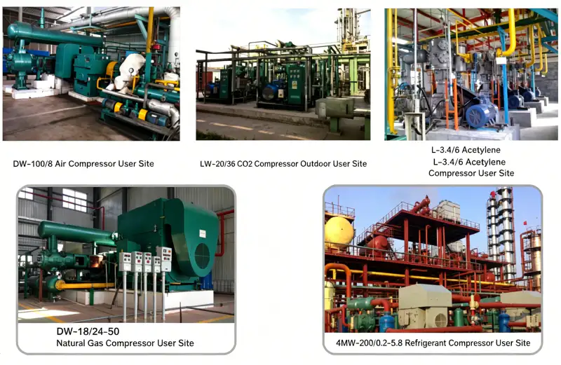
Case Study: Petrochemical Complex Nitrogen Distribution Overhaul
クライアント: A major petrochemical complex in the Middle East with three ethylene crackers, two polyethylene plants, and a polypropylene unit
チャレンジ: The complex’s nitrogen supply was provided by three aging oil-lubricated compressors (two European brands, one Asian brand, 16–22 years in service) feeding a common 0.60 MPa distribution header. The compressors were experiencing progressive oil carryover into the nitrogen stream, contaminating catalyst beds in the ethylene crackers and causing polymerization issues in the polyethylene reactors. Maintenance costs had escalated to $120,000/year, and the 0.60 MPa pressure was insufficient for new high-pressure reactor inerting requirements. The complex required a minimum 55 m³/min at 0.80 MPa to meet expanded production targets.
解決: 私たちは供給しました LW-60/8 oil-free nitrogen compressor as the new primary compressor, configured on a custom skid with integrated intercooler, aftercooler, and a Siemens S7-1200 PLC control panel with full SCADA integration. The 0.80 MPa discharge pressure met all new high-pressure inerting requirements, while the oil-free design eliminated contamination of catalyst beds and polymerization reactors. A 10 m³ surge vessel was installed upstream to buffer demand fluctuations from the multiple process units. The two existing compressors were retained as backup units.
24か月後の定量的な結果:
- 窒素油含有量: Reduced from 5.8 mg/m³ to <0.01 mg/m³ISO 8573-1クラス0認証を取得
- Catalyst bed replacement frequency: Extended from 18 months to 48 months, saving $180,000/year in catalyst costs
- Polymerization reactor contamination events: 完全に排除された, improving on-spec production by 2.1%
- Annual maintenance cost: Reduced by 48% ($120,000 to $62,400) through elimination of oil-related repairs
- エネルギー消費量: Improved by 8.2% versus the primary replaced unit, saving approximately $24,800/year
- 予期せぬシステム停止: イベントゼロ 24ヶ月間の連続稼働
“The LW-60/8 has completely transformed our nitrogen reliability. The elimination of oil contamination has extended our catalyst life by 2.5× and eliminated reactor contamination events. Our maintenance team has been redeployed to proactive tasks instead of constant oil-related repairs. The payback period was under 16 months.” — Chief Operations Officer, Petrochemical Complex
よくある質問と選択ガイド
関連製品およびソリューション
LW-52/8 High-Capacity Nitrogen Compressor
A slightly lower-capacity sibling delivering 52 m³/min at 0.80 MPa, ideal for applications where the full 60 m³/min of the LW-60/8 is not required. Offers identical oil-free technology and engineering standards.
DWシリーズ高圧窒素コンプレッサー
Designed for discharge pressures from 0.40 MPa to 2.00 MPa, the DW series covers nitrogen injection, high-pressure pipeline boosting, and chemical synthesis applications. Capacities from 2 to 130 m³/min.
ZWシリーズ 多段式オイルフリーコンプレッサー
Vertical, multi-stage oil-free compressors for oxygen, nitrogen, hydrogen, and specialty gases. Discharge pressures up to 9.00 MPa for high-pressure gas filling, cylinder charging, and chemical process applications.
当社の包括的な概要については、 工業用窒素圧縮機 オイルフリー酸素圧縮機、水素圧縮機、二酸化炭素圧縮機、および特注設計の特殊ガスソリューションを含む製品ポートフォリオの詳細については、当社のアプリケーションエンジニアリングチームにお問い合わせいただくか、オンライン製品カタログをご覧ください。
Ready to Transform Your Ultra-High-Capacity Nitrogen System?
当社のアプリケーションエンジニアが、お客様の窒素流量要件、吸引条件、吐出圧力目標、およびシステム統合上の制約を評価するために待機しております。お問い合わせをいただいてから48時間以内に、無料の技術提案書、基礎レイアウト図、配管計装図(P&ID)、および詳細な総所有コスト(TCO)分析をご提供いたします。
メールアドレス: [email protected] 24時間以内に返信いたします

























