Beschreibung
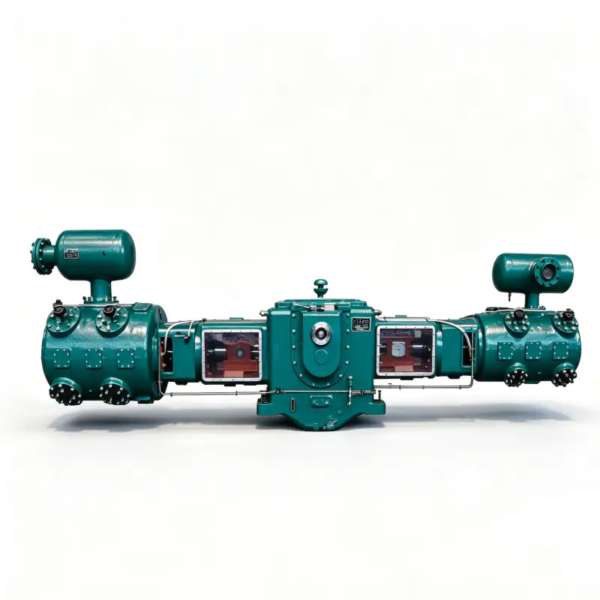
LW-50/8 Stickstoffkompressor – Ölfreier Hochleistungs-N2-Booster für industrielle Mitteldruckverteilung
Engineered to deliver 50 m³/min at 0.80 MPa discharge pressure, the LW-50/8 is a two-stage, two-row oil-free piston nitrogen compressor purpose-built for large-scale cryogenic air separation backup, high-pressure VPSA nitrogen boosting, and extensive industrial pipeline distribution networks. Zero lubricant contamination, continuous-duty rated, and optimized for demanding 24/7 industrial environments.
Produktübersicht
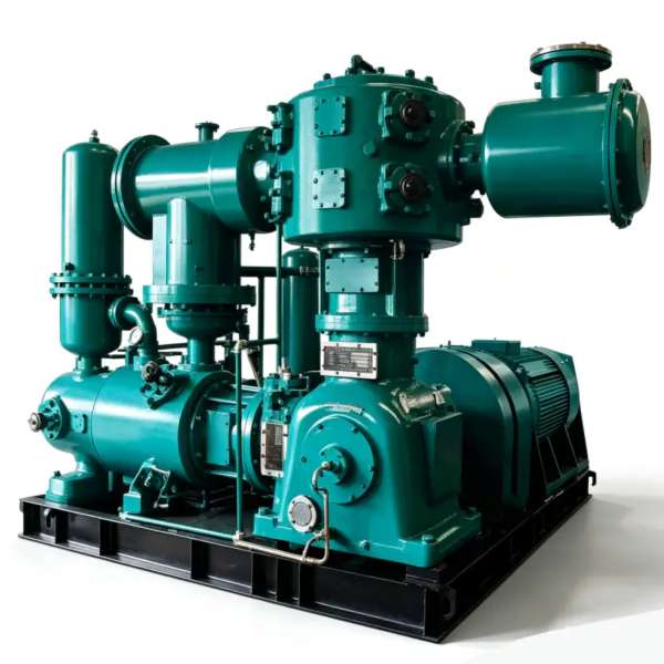
Der LW-50/8 nitrogen compressor stands as a high-capacity workhorse within our oil-free piston compressor lineup, engineered to bridge the demanding gap between primary nitrogen generation and medium-pressure distribution infrastructure. With an impressive rated capacity of 50 m³/min coupled with a robust discharge pressure of 0,80 MPa, this unit addresses the most challenging requirements of large-scale cryogenic air separation plants, high-pressure VPSA booster stations, and extensive petrochemical pipeline networks.
What fundamentally differentiates the LW-50/8 from conventional lubricated compressors is its entirely oil-free compression pathway. The piston rings and rider bands are precision-crafted from advanced self-lubricating PTFE composite formulations that function without any hydrocarbon-based lubricants. This intrinsic design ensures the nitrogen stream remains completely devoid of oil contamination—a non-negotiable attribute for applications mandating ISO 8573-1 Class 0 certification, encompassing food packaging nitrogen, pharmaceutical inerting, semiconductor process gas delivery, and high-purity chemical blanketing.
The compressor architecture implements a zweistufig, zweireihig (二列二级) configuration that strategically partitions the total pressure ratio across dual compression cylinders. This staged methodology reduces per-stage discharge temperatures, enhances volumetric efficiency, and significantly prolongs the operational lifespan of valves and piston rings. Each compression stage incorporates an independent intercooler, maintaining gas temperatures within safe thermal envelopes even during sustained maximum-load continuous operation. The reinforced cast-iron frame and precision-machined forged steel crankshaft assembly are rated for exceeding 100,000 hours of reliable service under standard preventive maintenance protocols.
Technical Specifications – LW-50/8
| Parameter | Wert | Einheit |
|---|---|---|
| Modell | LW-50/8 | – |
| Muster | Zweistufig, zweireihig (二列二级) | – |
| Kapazität | 50 | m³/min |
| Entladedruck | 0.80 | MPa |
| Kompressorgröße (L × B × H) | 2630 × 1600 × 2235 | mm |
| Gewicht | 6.50 | T |
| Leistung | 350 | kW |
| Stromspannung | 380 / 6k oder 10k | V |
| Gasmedium | Stickstoff (N₂) | – |
| Schmierung | Ölfrei | – |
* Alle Spezifikationen beziehen sich auf Standardreferenzbedingungen (ISO 1217, Anhang C). Die tatsächliche Leistung kann je nach Standorthöhe, Umgebungstemperatur und Einlassbedingungen variieren.
Hauptmerkmale und technische Vorteile
1. Advanced Oil-Free PTFE Composite Sealing System
The LW-50/8 deploys a proprietary selbstschmierende Kolbenring- und Führungsbandbaugruppe manufactured from high-density PTFE composites reinforced with glass fiber and bronze particulate additives. This advanced material matrix achieves a dynamic coefficient of friction below 0.07 without any external hydrocarbon lubrication, completely eliminating the risk of oil vapor carryover into the nitrogen product stream. For industrial buyers operating within regulated sectors, this translates directly to ISO 8573-1 Klasse 0-Konformität without the substantial capital investment and ongoing maintenance burden associated with downstream oil-filtration, coalescing, and activated carbon purification systems.
2. Optimized Two-Stage Thermodynamic Performance
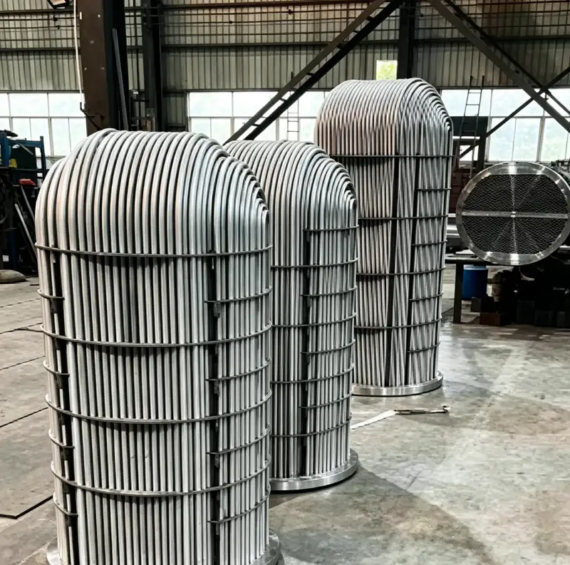
Der zweistufige Kompressionsarchitektur of the LW-50/8 is thermodynamically calibrated for the 0.80 MPa discharge pressure target. By distributing the pressure ratio between a dedicated low-pressure cylinder and a high-pressure cylinder, the compressor achieves a substantially lower mean effective temperature per individual stage. An engineered shell-and-tube intercooler positioned between stages efficiently removes the heat of compression, maintaining discharge temperatures consistently below 150°C even at maximum continuous rated load. This sophisticated thermal management strategy extends valve plate operational life by approximately 40% compared to single-stage compressors subjected to equivalent overall pressure ratios, while simultaneously reducing the risk of thermal polymerization in nitrogen streams containing trace oxygen impurities.
3. Heavy-Duty Force-Balanced Frame Construction
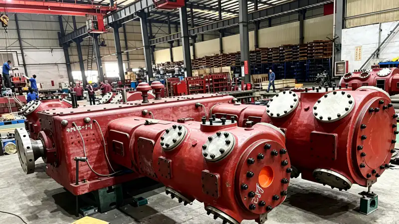
Der Hauptverdichterblock ist gegossen aus GG25 Grauguss (equivalent to ASTM A48 Class 30B) featuring integral cooling water passages machined directly into the casting. The two-row opposed-cylinder arrangement delivers inherent first-order force cancellation, reducing the unbalanced inertial forces transmitted to the foundation by over 85% compared to conventional single-row designs. This mechanical advantage permits the LW-50/8 to operate on a substantially lighter foundation block (minimum 10 tonnes versus 16+ tonnes for comparable single-row equivalents), significantly reducing civil engineering expenditure and simplifying retrofit installations within existing compressor houses or air separation facilities.
4. Flexible Multi-Voltage Motor Configuration
The LW-50/8 is driven by a 350 kW high-efficiency three-phase induction motor available in 380V, 6kV, or 10kV configurations conforming to IEC 60034-1 IE3 efficiency class. The 380V option integrates seamlessly into existing low-voltage industrial distribution infrastructure, while the 6kV and 10kV variants enable direct connection to medium-voltage bus systems prevalent in large-scale air separation and petrochemical facilities. This voltage flexibility eliminates the necessity for additional step-down transformers in medium-voltage environments, reducing electrical infrastructure capital costs and improving overall system energy efficiency by minimizing transformer losses.
Anwendungsszenarien
Large-Scale Cryogenic Air Separation Backup & Peak Shaving
Within cryogenic ASU operations, the LW-50/8 functions as a high-capacity backup nitrogen booster or peak-shaving compressor of exceptional reliability. When the primary air separation unit encounters a cold box upset, molecular sieve contamination event, or scheduled maintenance outage, the LW-50/8 can seamlessly maintain nitrogen supply to critical downstream consumers drawing from liquid nitrogen storage vaporizers. Its substantial 0.80 MPa discharge pressure provides ample head for feeding medium to high-pressure distribution headers serving steel mill inerting systems, chemical reactor blanketing, LNG plant purge gas networks, and pipeline injection stations. The oil-free design assumes paramount importance in backup scenarios where nitrogen purity integrity cannot be compromised during primary system unavailability.
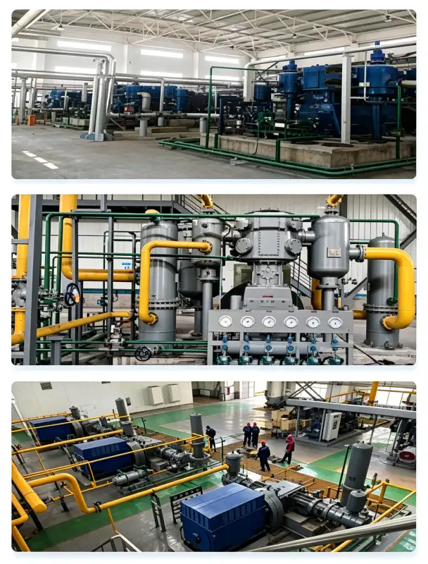
VPSA-Hochdruck-Stickstoff-Boosterstationen
Vacuum Pressure Swing Adsorption (VPSA) nitrogen generators produce gaseous nitrogen at near-atmospheric pressure (typically 0.05–0.10 MPa). The LW-50/8 nitrogen booster compresses this low-pressure product to 0.80 MPa for distribution to demanding point-of-use applications. The oil-free compression pathway is absolutely critical in VPSA service because any hydrocarbon contamination would irreversibly poison the carbon molecular sieve adsorbent, permanently degrading the nitrogen generator’s separation efficiency and necessitating costly complete adsorbent bed replacement. The 50 m³/min capacity matches the output of large VPSA installations producing 2,000–3,000 Nm³/h of 99.5–99.9% purity nitrogen.
Petrochemical & Refinery High-Pressure Pipeline Injection
Refinery tank farms, petrochemical storage terminals, and chemical process plants require substantial volumes of nitrogen for high-pressure tank blanketing, pipeline inerting, and process vessel purging to prevent explosive vapor formation and maintain product integrity. The LW-50/8’s 0.80 MPa discharge pressure delivers adequate head to overcome significant pipeline friction losses over distances exceeding 3 km, making it eminently suitable for centralized nitrogen supply architectures serving multiple process units, storage tanks, and loading stations simultaneously. The continuous-duty rating and high flow capacity ensure uninterrupted nitrogen availability during extended maintenance campaigns that may span several weeks.
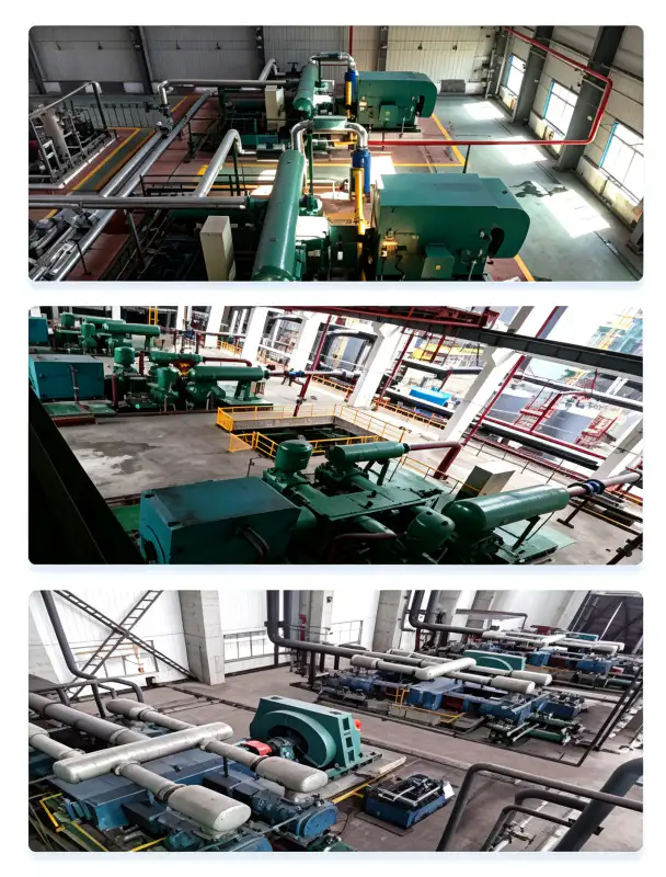
Food & Beverage High-Speed Modified Atmosphere Packaging
Large-scale food packaging facilities operating high-speed production lines require substantial nitrogen flow for Verpackung unter modifizierter Atmosphäre (MAP), controlled atmosphere storage, and nitrogen flushing of packaging equipment. The LW-50/8’s impressive 50 m³/min capacity can simultaneously supply numerous high-speed packaging lines, industrial-scale snack food production, dairy processing plants, and ready-meal manufacturing facilities. Its oil-free certification ensures full compliance with FDA 21 CFR 173.310 (food-grade nitrogen specifications) and EU Regulation 231/2012. The complete absence of oil contamination eliminates any risk of off-flavors, product rancidity, or discoloration that can occur when lubricated compressors are inadvertently deployed in food-contact nitrogen applications.
Material & Konstruktion
Every component of the LW-50/8 is meticulously selected for nitrogen service compatibility, corrosion resistance, and extended mechanical durability under demanding industrial conditions:
| Komponente | Material | Spezifikation |
|---|---|---|
| Zylinderblock | Grauguss | GG25 / HT250, integral cooling water jackets |
| Kurbelwelle | Geschmiedeter legierter Stahl | 42CrMo4, Q&T, ISO 1940 G2.5 dynamisch ausgewuchtet |
| Kolbenringe | PTFE-Glas-Bronze-Verbundwerkstoff | Self-lubricating, wear rate <0.04 mm/1000h |
| Reiterbänder | PTFE-Verbundwerkstoff | Kolbenführung, verhindert Zylinderwandkontakt |
| Ventilplatten | Edelstahl | SS316, spring-loaded concentric ring design |
| Pleuelstangen | Geschmiedeter Stahl mit Gleitlagern | Präzisionsgefertigtes, ölgeschmiertes Pleuelauge |
| Ladeluftkühler | Gehäuse aus Kohlenstoffstahl / Rohre aus Edelstahl SS304 | ASME VIII Div.1, 1,5× hydrostatischer Test |
| Ladeluftkühler | Gehäuse aus Kohlenstoffstahl / Rohre aus Edelstahl SS304 | Finned tube design, 32°C cooling water rated |
| Grundrahmen | Geschweißter Baustahl | Vibration-damped mounting with anchor templates |
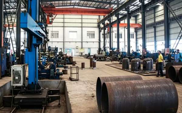
All pressure-bearing components are designed, fabricated, and tested in strict accordance with ASME BPVC Abschnitt VIII Division 1 or equivalent Chinese GB 150 standards. Every weld joint undergoes comprehensive 100% radiographic inspection (RT) per ASME Section V, Article 2, and each completed pressure vessel is subjected to a rigorous hydrostatic pressure test at 1.5 times the maximum allowable working pressure (MAWP) for a minimum hold duration of 30 minutes before factory release.
Installations- und Wartungsrichtlinien
Fundament- und Strukturanforderungen
The LW-50/8 has a dry weight of 6.50 tonnes with a center of gravity positioned approximately 900 mm above the baseplate. Thanks to the two-row opposed-cylinder design, unbalanced forces are minimized, permitting installation on a reinforced concrete inertia block of 10–12 tonnes. The block should be mounted on elastomeric vibration isolation pads (natural frequency 6–8 Hz) to prevent vibration transmission to adjacent structures and instrumentation. Minimum clearance requirements: 1.5 m on the non-drive side for valve access and maintenance, 1.2 m on the drive side for motor and coupling inspection, and 2.0 m overhead clearance for crane-assisted major overhauls.
Spezifikationen des Kühlwassersystems
Cooling water flow requirement is approximately 42 m³/h at an inlet temperature not exceeding 32°C. The cooling water distribution network must supply the cylinder jackets, intercooler, and aftercooler in parallel flow circuits. Water quality specifications: pH 6.5–8.5, total dissolved solids < 500 mg/L, chloride content < 50 mg/L (to prevent SS304 tube corrosion in coolers), and suspended solids < 30 mg/L. For facilities operating in tropical climates or with marginal water quality, a closed-loop cooling tower equipped with side-stream filtration and automated chemical treatment is strongly recommended to prevent scale formation and microbiological fouling in intercooler tubes.
Comprehensive Preventive Maintenance Schedule
| Intervall | Serviceartikel | Handlungsbedarf erforderlich |
|---|---|---|
| Täglich | Betriebsprüfung | Prüfen Sie Vibrationswerte, ungewöhnliche Geräusche, Kühlwasserdurchfluss und Auslauftemperatur. |
| 250 Stunden | Ventilplattenprüfung | Saug-/Druckventilplatten ausbauen und auf Kohlenstoffablagerungen oder Risse prüfen. |
| 1.000 Stunden | Beurteilung des Kolbenringverschleißes | Messen Sie das Spiel in der Kolbenringnut; ersetzen Sie die Kolbenringe, wenn das Spiel 0,25 mm überschreitet. |
| 4.000 Stunden | Zwischenüberholung | Alle Kolbenringe, Ventilkegel und Ventilplatten austauschen |
| 8.000 Stunden | Generalüberholung | Prüfen Sie die Kurbelwellenzapfen, messen Sie das Lagerspiel und ersetzen Sie die Hauptlager, wenn es >0,08 mm beträgt. |
A defining economic advantage of the LW-50/8 is the complete elimination of lubricating oil from the compression pathway. Unlike oil-lubricated compressors that demand quarterly oil changes, monthly oil analysis, annual separator element replacement, and waste oil disposal, the LW-50/8 removes these consumables entirely. The sole recurring wear items are the PTFE-Kolbenringe und -Zündbänder, which consistently achieve 4,000–6,000 hours of reliable service under clean nitrogen operating conditions.
Konformitäts- und Sicherheitszertifizierungen
The LW-50/8 nitrogen compressor is designed, manufactured, and tested to satisfy the following international standards and regulatory frameworks:
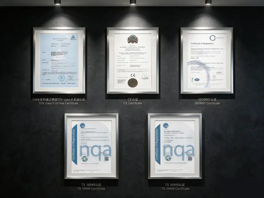
ASME BPVC Abschnitt VIII Div.1, GB 150-2011, PED 2014/68/EU Modul A
IEC 60034-1 (IE3 efficiency class), IEC 60204-1, ISO 12100
ISO 8573-1 Klasse 0 (Ölgehalt), unabhängig geprüft vom TÜV Rheinland
ISO 9001:2015, ISO 14001:2015
Nitrogen is classified as an odorless, colorless simple asphyxiant gas. All LW-50/8 installations must incorporate continuous oxygen deficiency monitoring within the compressor room and all adjacent enclosed areas. Ventilation systems must be engineered to maintain ambient oxygen concentrations above 19.5% by volume per OSHA 29 CFR 1910.146 (Permit-Required Confined Spaces). Emergency shutdown interlocks should activate at 19.5% O₂ (alarm condition) and trigger automatic compressor isolation at 18.0% O₂ (hard shutdown). Personnel entry procedures into enclosed compressor rooms must mandate portable oxygen monitors and strict buddy-system protocols.
Leistungs- und Effizienzanalyse
The LW-50/8 achieves a specific power consumption of approximately 7.00 kW per m³/min of nitrogen delivered at 0.80 MPa discharge pressure. This efficiency metric positions the unit competitively within the high-capacity oil-free piston compressor segment for medium-pressure applications. For comparative context, oil-lubricated screw compressors operating at equivalent pressure ratios typically consume 7.5–8.5 kW/m³/min, while legacy single-stage piston designs may exceed 9.0 kW/m³/min at this pressure level.
Over a standard 8,000-hour annual operating schedule, the LW-50/8’s efficiency advantage generates approximately 200,000–400,000 kWh of annual energy savings compared to less efficient alternatives. At an average industrial electricity tariff of $0.08/kWh, this translates to $16,000–$32,000 in direct annual operating cost reduction. When combined with the complete elimination of oil-related consumables (lubricating oil, filter elements, separator cartridges, waste oil disposal), the Gesamtbetriebskosten für die Stickstoffkompression is reduced by an estimated 28–38% over a 10-year operational lifecycle.
The absence of oil in the compression pathway additionally eliminates the energy penalty associated with downstream oil-removal equipment. A typical oil-lubricated compressor of this capacity requires coalescing filters, activated carbon adsorbers, and continuous oil monitoring instrumentation that collectively consume 3–5% of the compressor’s rated power output. The LW-50/8’s oil-free architecture removes this parasitic energy drain entirely.
Anpassungs- und OEM-Fähigkeiten
We offer extensive customization options to adapt the LW-50/8 to specific site conditions, integration requirements, and end-user operational specifications:
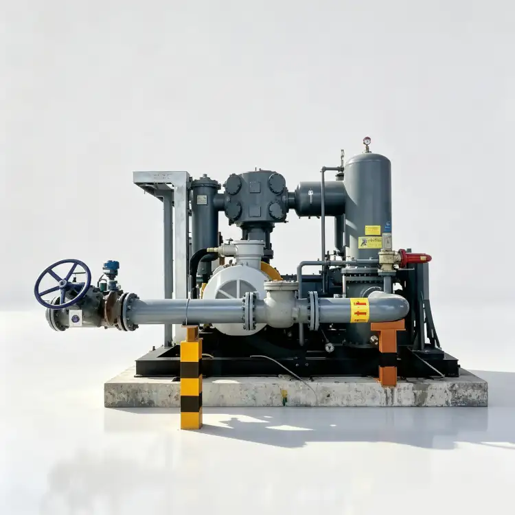
- Auf Kufen montierte, schlüsselfertige Pakete: Complete compressor, motor, intercooler, aftercooler, instrumentation, and control panel pre-assembled on a heavy-duty structural steel skid with integrated lifting lugs and precision anchor bolt templates. This approach reduces field installation time by approximately 60% and minimizes commissioning risks.
- Konfigurationen von Gefahrenbereichen: ATEX Zone 2 and IECEx compliant motor and electrical enclosures for installations in petrochemical facilities where explosive atmospheres may occasionally be present. Integrated gas detection and automatic ventilation interlocks can be incorporated into the control architecture.
- Advanced Process Control Systems: Optional Siemens S7-1200 or Allen-Bradley CompactLogix PLC with 10-inch HMI touchscreen, remote monitoring via Modbus TCP/IP or OPC-UA, and seamless DCS/SCADA integration. Automatic load/unload control and variable frequency drive (VFD) compatibility optimize part-load efficiency across varying demand profiles.
- Umweltschutzsysteme: C5-M marine-grade coating systems for coastal or offshore installations; tropicalized electrical components rated for ambient temperatures up to 55°C; and IP54-rated acoustic enclosures reducing noise emission from 85 dB(A) to 72 dB(A) at 1 meter, suitable for indoor installations without dedicated compressor houses.
- OEM- und Private-Label-Programme: Custom paint colors, branded nameplates, and comprehensive documentation packages for system integrators and gas equipment distributors. Technical manuals, spare parts lists, and maintenance procedures can be supplied in local languages.
Kundenspezifische Konfigurationen sind erhältlich bei Mindestbestellmenge: 1 Stück. Engineering review and detailed proposal generation typically require 5–7 business days. Prototype delivery schedules range from 12–14 weeks; serial production orders are delivered in 8–10 weeks from order confirmation.
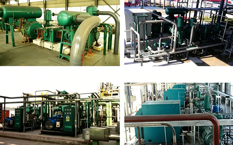
Case Study: Cryogenic ASU High-Pressure Nitrogen Booster Retrofit
Kunde: A leading industrial gas producer operating a cryogenic air separation facility in Thailand
Herausforderung: The client’s existing oil-lubricated nitrogen booster (European OEM, 14 years in service) was experiencing progressive oil carryover into the nitrogen product stream. Oil contamination levels reached 3.5 mg/m³, far exceeding the 0.1 mg/m³ limit contractually required by their food packaging and pharmaceutical customers. The oil contamination was also degrading the activated carbon final-polishing bed, necessitating replacement every 6 months instead of the designed 24-month interval, and causing frequent unplanned shutdowns for filter maintenance.
Lösung: Wir lieferten einen LW-50/8 oil-free nitrogen compressor as a direct replacement, engineered on a custom skid with integrated intercooler, aftercooler, and a Siemens S7-1200 PLC control panel with remote monitoring capability. The skid footprint was precisely designed to match the existing foundation, eliminating all civil modification requirements. A 3 m³ surge vessel was installed upstream to dampen pressure pulsations from the ASU cold box.
Quantifizierte Ergebnisse nach 30 Monaten:
- Stickstoffgehalt des Öls: Reduzierung von 3,5 mg/m³ auf <0,01 mg/m³, Erreichen der ISO 8573-1 Klasse 0 Zertifizierung
- Austauschintervall für das Aktivkohlebett: Verlängert von 6 Monaten auf 36 MonateEinsparung von 18.000 TP4T pro Jahr an Verbrauchsmaterialien
- Gesamte Instandhaltungskosten: Verringert um 451 TP3T through elimination of oil changes, filter replacements, and separator overhauls
- Energieverbrauch: Improved by 9.2% versus the replaced unit, equivalent to $22,000/year savings at local electricity rates
- Ungeplante Ausfallzeiten: Null Ereignisse in 30 Monaten ununterbrochenem Betrieb
- Customer complaints: Eliminated entirely since commissioning
“The LW-50/8 completely resolved our nitrogen purity challenges. Our food and pharmaceutical customers have noticed the improvement in product consistency, and our maintenance team has reduced their service time by nearly half. The investment paid for itself in under 20 months.” — Leiter der Anlagentechnik
Häufig gestellte Fragen & Auswahlhilfe
Verwandte Produkte und Lösungen
DW-Serie Hochdruck-Stickstoffkompressoren
Engineered for discharge pressures from 0.40 MPa to 2.00 MPa, the DW series addresses nitrogen injection, high-pressure pipeline boosting, and chemical synthesis applications. Capacities range from 2 to 130 m³/min with two-stage and multi-stage configurations.
Mehrstufige ölfreie Kompressoren der ZW-Serie
Vertikale, mehrstufige ölfreie Kompressoren für Sauerstoff, Stickstoff, Wasserstoff und Spezialgase. Förderdrücke bis zu 9,00 MPa für Hochdruckgasabfüllung, Zylinderbefüllung und Anwendungen in der chemischen Verfahrenstechnik.
Mitteldruckkompressoren der MW-Serie
Medium-pressure oil-free compressors (1.0–4.0 MPa) optimized for nitrogen recycle, gas liquefaction booster duty, and process gas compression in petrochemical and refinery operations.
Für einen umfassenden Überblick über unsere Industrieller Stickstoffkompressor product range, including oil-free oxygen compressors, hydrogen compressors, carbon dioxide compressors, and custom-engineered specialty gas solutions, please contact our application engineering team or browse our online product catalog.
Sind Sie bereit, Ihr Stickstoffkompressionssystem zu optimieren?
Unsere Anwendungstechniker stehen bereit, Ihre Anforderungen an den Stickstoffdurchfluss, die Ansaugbedingungen, die Zielvorgaben für den Förderdruck und die Integrationsbeschränkungen zu analysieren. Innerhalb von 48 Stunden nach Eingang Ihrer Anfrage erhalten Sie von uns kostenlose technische Angebote, Fundamentpläne, Rohrleitungs- und Instrumentierungsdiagramme (R&I-Fließbilder) sowie detaillierte Gesamtbetriebskostenanalysen (TCO).
E-Mail: [email protected] | Antwort innerhalb von 24 Stunden