
کمپریسڈ نائٹروجن میں آلودگی کی روک تھام
اس کے ماخذ کا سراغ لگا کر، نمونے کے نکات کی وضاحت کرکے، گیس کے راستے کی حفاظت کرکے، اور یہ ماننے کے بجائے کہ نائٹروجن خود بخود صاف ہے علاج کی تصدیق کرکے آلودگی کو کنٹرول کریں۔
نائٹروجن کی پاکیزگی اور نائٹروجن کی صفائی مختلف وضاحتیں ہیں۔ ایک گیس بہت کم آکسیجن پر مشتمل ہو سکتی ہے پھر بھی تیل ایروسول، پانی کے بخارات، ذرات، زنگ، مہر کا ملبہ، یا دیکھ بھال کی باقیات لے جاتی ہے۔ اس لیے کمپریسر سسٹم کو آکسیجن کے ارتکاز سے آزادانہ طور پر آلودگی کا انتظام کرنا چاہیے۔ یہ بتا کر شروع کریں کہ عمل کیا برداشت کر سکتا ہے، پھر نائٹروجن کی پیداوار اور استعمال کے مقام کے درمیان ہر ذریعہ کا نقشہ بنائیں۔ ان مقامات پر نمونہ جو اپ اسٹریم ٹریٹمنٹ کو کمپریسر سے پیدا ہونے والی آلودگی سے ممتاز کرتے ہیں۔ اصل صفائی کی ضرورت سے فلٹرز، ڈرائر، الگ کرنے والے، اور تیل سے پاک یا چکنا کرنے والی کمپریشن ٹیکنالوجی کا انتخاب کریں، اور دیکھ بھال کے بعد کارکردگی کی تصدیق کریں۔ مقصد فلٹرز کی زیادہ سے زیادہ تعداد کو انسٹال کرنا نہیں ہے۔ یہ جاننا ہے کہ کون سی رکاوٹ ہر آلودگی کو کنٹرول کرتی ہے اور کس طرح ناکام رکاوٹ کا پتہ لگایا جائے گا۔
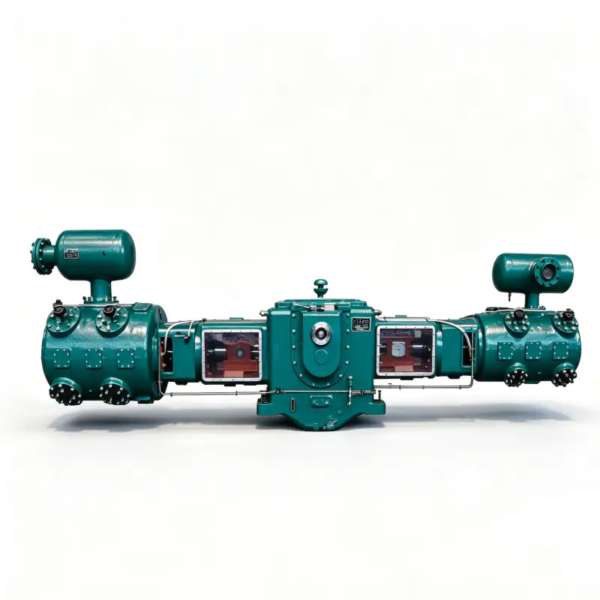
آلودگی اور کنٹرول رکاوٹیں۔
- تیل ایروسول
- باریک چکنا کرنے والی بوندیں یا بخارات جو تیل کے انجیکشن والے ذریعہ، چکنا کمپریسر، الگ کرنے والے کیری اوور، یا آلودہ پائپنگ سے گیس میں داخل ہو سکتے ہیں۔
- پانی کے بخارات
- گیس میں بخارات کے طور پر موجود نمی، جو اکثر نظر آنے والے مائع کی بجائے اوس کے نقطہ یا ارتکاز کے ذریعے بیان کی جاتی ہے۔
- ذرات کی آلودگی
- ٹھوس مواد جیسے زنگ، ڈیسیکینٹ ڈسٹ، پائپ پیمانہ، مہر کے ٹکڑے، یا گیس کے ذریعے منتقل کیا جانے والا تعمیراتی ملبہ۔
- کولیسنگ فلٹر
- ایک فلٹر جو باریک مائع ایروسول کو بڑی بوندوں میں ملانے کے لیے ڈیزائن کیا گیا ہے جو اس کی درجہ بندی کی کارکردگی کے اندر ذرات کو ہٹانے کے ساتھ ساتھ نالی بھی کر سکتا ہے۔
- ڈرائر
- وہ سامان جو پانی کے بخارات کو متعین دباؤ اور بہاؤ کے حالات میں ایک مخصوص اوس پوائنٹ یا نمی کی سطح تک کم کرتا ہے۔
- گیس کی طرف کی صفائی
- پروڈکٹ نائٹروجن کے سامنے آنے والی تمام سطحوں کی حالت، بشمول سلنڈر، والوز، پائپنگ، ریسیورز، کولر، سیل، اور دیکھ بھال کے اوزار۔
1. عمل میں آلودگی کی حد کی وضاحت کریں، کمپریسر بروشر پر نہیں۔
پوچھیں کہ نائٹروجن کیا رابطہ کرتی ہے۔ لیزر کٹنگ، فوڈ پیکیجنگ، سیمی کنڈکٹر ٹولز، فارماسیوٹیکل پروسیس، ٹینک بلینکیٹنگ، اور عام انارٹنگ میں تیل، نمی اور ذرات کے لیے بہت مختلف رواداری ہوسکتی ہے۔ بیان کردہ دباؤ اور نمونے لینے کے مقام پر اس ضرورت کو قابل پیمائش گیس کے معیار کی ضروریات میں ترجمہ کریں۔ اکیلے آکسیجن کی پاکیزگی اس بات کا جواب نہیں دیتی کہ آیا گیس مصنوعات کے رابطے یا حساس آلات کے لیے کافی صاف ہے۔
جہاں باضابطہ کوالٹی اسٹینڈرڈ یا گاہک کی تفصیلات لاگو ہوتی ہیں، اس کی پیمائش کا طریقہ اور حد استعمال کریں۔ جہاں عمل کا مالک صرف مبہم زبان فراہم کرتا ہے جیسے کہ صاف یا خشک نائٹروجن، کمپریسر کے انتخاب سے پہلے اس ابہام کو دور کریں۔ تیل سے پاک گیس کا راستہ آلودگی کے ایک منبع کو ہٹا سکتا ہے لیکن اوپر کی طرف متعارف کرائی جانے والی خستہ حال پائپنگ یا نمی سے ذرات کو نہیں ہٹاتا ہے۔
2. تیل، پانی، اور ذرات کے لیے ماخذ کا نقشہ بنائیں
مقام کے لحاظ سے ہر ممکنہ ذریعہ کی فہرست بنائیں۔ تیل فیڈ ایئر کمپریسرز، چکنا نائٹروجن کمپریسرز، پمپ، اسمبلی چکنائی، یا آلودہ ریسیورز میں پیدا ہو سکتا ہے۔ پانی ناکافی ڈرائر سے گزر سکتا ہے، ٹھنڈا ہونے کے بعد گاڑھا ہو سکتا ہے، شٹ ڈاؤن کے دوران داخل ہو سکتا ہے، یا ہائیڈرو سٹیٹک کام کے بعد رہ سکتا ہے۔ ذرات فلٹرز، ڈیسیکینٹ، ویلڈنگ اسکیل، زنگ، سیل اور دیکھ بھال کے ملبے سے آسکتے ہیں۔ ماخذ کا نقشہ صفائی کے عمومی مسئلے کو قابل امتحان شاخوں میں بدل دیتا ہے۔
اہم رکاوٹوں سے پہلے اور بعد میں نمونہ پوائنٹس کو نشان زد کریں۔ مثال کے طور پر، نائٹروجن جنریٹر آؤٹ لیٹ پر ایک نمونہ آنے والے معیار کو قائم کرتا ہے۔ بوسٹر کے بعد ایک سیکنڈ ظاہر کرتا ہے کہ آیا کمپریشن نے اسے تبدیل کیا ہے۔ حتمی فلٹر کے بعد ایک نقطہ ڈیلیور شدہ حالت کی تصدیق کرتا ہے۔ اگر صرف حتمی ہیڈر کا نمونہ لیا جاتا ہے، تو برا نتیجہ آپ کو بتاتا ہے کہ سسٹم ناکام ہوا لیکن کہاں نہیں۔
درخواست کے لیے مخصوص کراس چیک کے لیے، سائٹ کا استعمال کریں۔ تیل سے پاک نائٹروجن کمپریسر اوپر زیر بحث ڈیوٹی ڈیٹا کے ساتھ صفحہ۔ یہاں کراس چیک کمپریسڈ میں تیل کی نمی کے ذرہ کی آلودگی کو روکنے کے لیے بندھا ہوا ہے۔
3. فلٹریشن اور خشک کرنے والے کو آلودگی کے طریقہ کار سے ملا دیں۔
کوالیسنگ فلٹر اس کی درجہ بندی کی حد کے اندر ایروسول اور ذرات کے لیے مفید ہے، لیکن جب ضرورت پانی کے بخارات سے متعلق ہو تو یہ ڈرائر کا متبادل نہیں ہے۔ اسی طرح، ڈرائر تیل سے پاک گیس کی ضمانت نہیں دیتا۔ داخلی ارتکاز، مطلوبہ آؤٹ لیٹ کی حالت، دباؤ، درجہ حرارت، اور بہاؤ کے لیے علاج کے ہر مرحلے کا انتخاب کریں۔ تفریق دباؤ کی نگرانی شامل کریں جہاں فلٹر لوڈنگ کمپریسر سکشن یا ڈسٹری بیوشن پریشر کو محدود کر سکتا ہے۔
الگ کرنے والے اور نالیاں رکھیں جہاں ٹھنڈک مائع پیدا کر سکے۔ ایک سیر شدہ فلٹر عنصر، ناکام آٹومیٹک ڈرین، یا اوورلوڈڈ سیپریٹر آلودگی کو دوبارہ داخل کر سکتا ہے۔ استعمال کے مقام پر نظر آنے والے کیری اوور کا انتظار کرنے کے بجائے تفریق دباؤ، ڈرین رویے، معیار کے نتائج، اور سپلائر کی رہنمائی سے معائنہ اور متبادل معیار قائم کریں۔

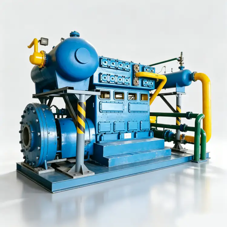
4. آپریشن اور دیکھ بھال کے دوران کمپریسر گیس سائیڈ کی صفائی کی حفاظت کریں۔
اگر عمل کو تیل سے پاک راستے کی ضرورت ہے تو تصدیق کریں کہ کمپریسر کے کون سے اجزاء دراصل چکنا کرنے والے سے الگ تھلگ ہیں۔ تیل سے پاک کے طور پر مارکیٹ کی جانے والی مشین کا ابھی بھی بیئرنگ سیل، فاصلے کے ٹکڑوں، صاف کرنے کے انتظامات، اور کسی ایسے معاون نظام کا جائزہ لیا جانا چاہیے جو گیس کے ساتھ بات چیت کر سکے۔ چکنا ہوا کمپریشن کے لیے، علیحدگی کی کارکردگی کو سمجھیں اور کیا نیچے کی طرف سے علاج تمام آپریٹنگ ریاستوں میں عمل کی ضرورت کو پورا کر سکتا ہے۔
دیکھ بھال ایک عام آلودگی کا واقعہ ہے۔ حساس سروس کے لیے کلین ٹولز، ہم آہنگ وائپس اور چکنا کرنے والے مادے، کیپ شدہ اجزاء، اور کنٹرول شدہ اسمبلی ایریاز کا استعمال کریں۔ کھلی پائپنگ کو دھول یا نمی کے سامنے نہ چھوڑیں۔ والوز، پیکنگ، فلٹرز، یا کولرز کو تبدیل کرنے کے بعد، سسٹم کو اہم صارفین کے لیے جاری کرنے سے پہلے گیس کے معیار کو صاف اور تصدیق کریں۔
5. ناکام ہونے والی رکاوٹوں کو تلاش کرنے کے لیے نمی اور آلودگی کے رجحانات کا استعمال کریں۔
ایک بار پاس کا نتیجہ اہم نائٹروجن کے لیے کافی نہیں ہے۔ ٹرینڈ اوس پوائنٹ یا نمی، تیل جہاں ضرورت ہو، فلٹر ڈیفرینشل پریشر، ڈرین ایکٹیویٹی، اور ذرہ کے نتائج ایک فریکوئنسی پر جو رسک پر کارروائی کرتے ہیں۔ نمی میں بتدریج اضافہ ڈرائر کے انحطاط کی نشاندہی کر سکتا ہے۔ سروس کے بعد اچانک قدم گیلی پائپنگ یا والو کی غلط لائن اپ کی نشاندہی کر سکتا ہے۔ تیل سے پاک بوسٹر کا غیر متوقع تیل نیچے کی طرف متوجہ ہوتا ہے نہ کہ براہ راست کمپریسر کو مورد الزام ٹھہرانے کی بجائے اوپر کی طرف یا دیکھ بھال کی آلودگی کی طرف۔
درجہ حرارت اور دباؤ کے ساتھ معیار کی تبدیلیوں کو جوڑیں۔ مثال کے طور پر اوس پوائنٹ کے آلات کو نمونے لینے کی مخصوص حالت پر استعمال کیا جانا چاہیے۔ غیر گرم نمونہ لائن میں گاڑھا ہونا ریڈنگ کو بگاڑ سکتا ہے۔ نمونے لینے کے طریقہ کار کا استعمال کریں جو مقام، دباؤ میں کمی، صاف کرنے کا وقت، بہاؤ، اور آلے کی حالت کا تعین کرتا ہے تاکہ رجحانات متضاد تکنیک کے بجائے گیس کی عکاسی کریں۔
فیلڈ کی حالت کی تصدیق کرنے کے بعد، سائٹ کا جائزہ لیں۔ ہوا کی علیحدگی کے لیے نائٹروجن کمپریسر ایک حقیقت پسندانہ کمپریسر فیملی کے ساتھ ضرورت کو پورا کرنے کے لیے وسائل۔ یہاں کراس چیک کمپریسڈ میں تیل کی نمی کے ذرہ کی آلودگی کو روکنے کے لیے بندھا ہوا ہے۔
6. کمپریسر کے کام کرنے کے بعد ڈاون اسٹریم سسٹم کو صاف رکھیں
فائنل ریسیورز اور پلانٹ پائپنگ صاف نائٹروجن کو دوبارہ آلودہ کر سکتے ہیں۔ نئے کاربن سٹیل پائپ پیمانے پر بہایا جا سکتا ہے؛ پرانے ہیڈر پچھلی سروس سے تیل پر مشتمل ہوسکتے ہیں؛ مردہ ٹانگیں نمی برقرار رکھ سکتی ہیں۔ کمپریسر آؤٹ لیٹ سرٹیفکیٹ یا کمیشننگ نمونے پر بھروسہ کرنے سے پہلے تقسیم کے نظام کو اس سطح پر صاف، خشک اور صاف کریں۔
جب عمل کا خطرہ حتمی رکاوٹ کو جواز بناتا ہے تو پوائنٹ آف استعمال فلٹریشن کا استعمال کریں، لیکن اسے آلودہ مرکزی نظام کو چھپانے کے لیے استعمال نہ کریں۔ پوائنٹ فلٹرز کو قابل رسائی رہائش، تفریق دباؤ یا سروس کے معیار، ہم آہنگ مواد، اور کنٹرول شدہ عنصر کی تبدیلی کی ضرورت ہے۔ بہترین آلودگی پروگرام حتمی کنکشن کے ذریعے ماخذ گیس سے ہر رکاوٹ کو ملکیت تفویض کرتا ہے۔
آلودگی پر قابو پانے کی میز
| آئٹم | انجینئرنگ کا سوال | تصدیق یا فیصلے کا اشارہ |
|---|---|---|
| تیل کا کنٹرول | چکنا کرنے والا نائٹروجن کے راستے میں کہاں داخل ہو سکتا ہے؟ | کمپریشن سے پہلے اور بعد میں نمونے لینے سے کمپریسر کیری اوور سے ماخذ کی آلودگی میں فرق ہوتا ہے۔ |
| نمی کنٹرول | صارف کو اوس پوائنٹ یا نمی کی کس حد کی ضرورت ہے؟ | ڈرائر اور سیمپل سسٹم کا انتخاب اور تصدیق شدہ دباؤ اور بہاؤ پر کیا جاتا ہے۔ |
| ذرات | کون سے اجزاء ملبے کو بہا سکتے ہیں؟ | فلٹرز، پائپنگ کی صفائی، اور دیکھ بھال کے کنٹرول اصل ذرہ ذرائع سے خطاب کرتے ہیں۔ |
| تصدیق | کیا برے نتیجے کو جلدی سے مقامی کیا جا سکتا ہے؟ | متعدد متعین نمونہ پوائنٹس اپ اسٹریم، کمپریسر، علاج، اور تقسیم کی وجوہات کو الگ کرتے ہیں۔ |
| حتمی بنیاد کو RFQ، کمیشننگ فائل، یا دیکھ بھال کے ریکارڈ میں ریکارڈ کریں تاکہ کوئی دوسرا انجینئر فیصلے کو دوبارہ پیش کر سکے۔ | ||
پروجیکٹ کی توثیق کی ورک شیٹ
باؤنڈری پر "آلودگی کے ذریعہ کی شناخت" کی تصدیق کریں جہاں اس کا نتیجہ ظاہر ہوتا ہے۔ آئل ایروسول کو اس کے منبع پر دیکھیں اور وصول کرنے والے حصے پر ذرات کی آلودگی کا مشاہدہ کریں، پھر مکمل کریں "استعمال کے مقام پر تیل، نمی، ذرہ، اور آکسیجن کی ضروریات کو الگ الگ بیان کریں۔" جبکہ متعلقہ بہاؤ اور دباؤ مستحکم ہیں۔ سامان کی خرابی سے معمول کے عمل میں فرق کرنے کے لیے کافی سیاق و سباق کو ریکارڈ کریں۔ جب قبولیت کی درست حدیں منتخب ماڈل پر منحصر ہوں، تو موجودہ مینوفیکچرر دستاویزات یا منظور شدہ پروجیکٹ کی تفصیلات استعمال کریں۔ کسی دوسرے کمپریسر سے کسی قدر کو محض اس لیے منتقل نہ کریں کہ سروس ایک جیسی لگتی ہے۔ باؤنڈری ٹو باؤنڈری ریکارڈ بعد میں ٹربل شوٹنگ کو بہت تیز کرتا ہے۔
"نائٹروجن جنریشن سے صارف تک آلودگی کے ہر ممکنہ ذریعہ کا نقشہ بنائیں" پر لوپ بند کریں۔ وجہ، جواب، اور قبولیت کی دستاویز کے ذریعے۔ "متعین پوائنٹس پر نمونہ" کے ساتھ شروع کریں، آبی بخارات کے متوقع رویے کی نشاندہی کریں، اور ایک دوسرے مشاہدے کا انتخاب کریں جس میں کولیسنگ فلٹر شامل ہو جو آزادانہ طور پر اسی نتیجے کی تصدیق کر سکے۔ حفاظتی آلات کو نظرانداز کیے بغیر یا منظور شدہ آپریٹنگ رینج سے تجاوز کیے بغیر چیک کریں۔ اگر دونوں سگنل متفق نہیں ہیں، تو یہ فیصلہ کرنے سے پہلے کہ کون سا جزو کام کرنے کی ضرورت ہے، آلے کی درستگی، والو کی حالت، دباؤ میں کمی، آلودگی، رساو یا کنٹرول منطق کی چھان بین کریں۔ جب بند یا متبادل مہنگا ہو گا تو آزاد تصدیق قیمتی ہے۔
جائزے کے آئٹم کو "اپ اسٹریم ٹریٹمنٹ کی تصدیق کریں" کو ایک ریکارڈ شدہ قبولیت کے مرحلے میں تبدیل کریں۔ شناخت کریں کہ ذرات کی آلودگی کہاں دیکھی گئی ہے، اس وقت آپریٹنگ حالت، اور کون سی اپ اسٹریم یا ڈاون اسٹریم حالت ڈرائر کو تبدیل کر سکتی ہے۔ بنیاد قائم کرنے کے لیے استعمال ہونے والے آلے، ڈرائنگ، ڈیٹا شیٹ، یا جسمانی معائنہ کو ریکارڈ کریں۔ پھر "نمونہ پوائنٹس انسٹال کریں جو اپ اسٹریم، کمپریسر، ٹریٹمنٹ، اور ڈسٹری بیوشن کی کارکردگی کو الگ تھلگ کر سکتے ہیں" کو انجام دیں۔ دہرانے والی حالت کے تحت۔ اگر نتیجہ متوقع رویے سے متصادم ہے، تو اگلے ڈیزائن یا دیکھ بھال کے فیصلے کو اس وقت تک روکیں جب تک کہ تضاد کی وضاحت نہ ہوجائے۔ یہ ایک اور انجینئر کو میموری یا غیر دستاویزی مفروضے پر بھروسہ کیے بغیر چیک کو دوبارہ پیش کرنے کے لیے کافی سیاق و سباق فراہم کرتا ہے۔
کولیسنگ فلٹر کو فیلڈ چیک پوائنٹ کے طور پر استعمال کریں جو "کولسنگ فلٹرز، ڈرائر، سیپریٹرز، اور نالیوں کو ان کے اصل آلودگی والے میکانزم سے میچ کریں۔" پیمائش یا معائنہ کا مقام، گیس کی حالت، کمپریسر کا بوجھ، متعلقہ والو کی پوزیشنیں، اور دستاویز جو قبولیت کی وضاحت کرتی ہے لکھیں۔ ایک ہی وقت میں گیس کے اطراف کی صفائی کی جانچ پڑتال کریں تاکہ کسی مقامی علامت کو پورے نظام کے مسئلے کے لیے غلط نہ سمجھا جائے۔ تصور "کمپریسر گیس پاتھ کا معائنہ کریں" صرف اس وقت مکمل ہوتا ہے جب مشاہدہ ایک واضح فیصلے کی طرف لے جاتا ہے: سپلائر کے جائزے کے لیے قبول کریں، درست کریں یا بڑھا دیں۔ کسی بھی تصحیح کے بعد چیک کو دہرائیں اور کمیشننگ یا دیکھ بھال کے ریکارڈ کے ساتھ پہلے اور بعد کی اقدار رکھیں۔
متعلقہ آلات کے بینچ مارک کے لیے، سائٹ کا جائزہ لیں۔ نائٹروجن کمپریسر کا سائز اس سیکشن میں آپریٹنگ مفروضوں کی جانچ کے دوران اختیارات۔ یہاں کراس چیک کمپریسڈ میں تیل کی نمی کے ذرہ کی آلودگی کو روکنے کے لیے بندھا ہوا ہے۔
ایک کنٹرول کنڈیشن بنا کر جس میں ڈرائر اور آئل ایروسول کی ایک ساتھ تشریح کی جا سکتی ہے "کنڈینسیٹ ڈرین چیک کریں" کی تصدیق کریں۔ سسٹم کو مستحکم کریں، دباؤ، درجہ حرارت، بہاؤ، یا مشین کی حالت کو متعلقہ کے طور پر نوٹ کریں، اور نامزد کردہ مقامات پر کیلیبریٹڈ آلات یا براہ راست معائنہ کا استعمال کریں۔ "گیس کا راستہ کھولنے کے بعد صفائی کی دیکھ بھال کے کنٹرول شدہ طریقوں کا استعمال کریں اور صاف کریں۔" اور متوقع اور مشاہدہ شدہ دونوں ردعمل کو ریکارڈ کریں۔ اگر ماڈل کے لیے مخصوص حد کی ضرورت ہو تو اسے عام قدر ڈالنے کے بجائے منتخب کمپریسر، برتن، پائپنگ، جنریٹر، یا پراسیس دستاویزات سے حاصل کریں۔ ریکارڈ کو ظاہر کرنا چاہیے کہ حتمی فیصلہ تکنیکی طور پر قابل دفاع کیوں ہے۔
حفاظت اور تصدیق کی حد
نائٹروجن کے نمونے لینے اور نکالنے سے آکسیجن کی کمی کا ماحول پیدا ہو سکتا ہے، اور فلٹر یا ڈرائر ہاؤسنگ کمپریسر کے رکنے کے بعد دباؤ برقرار رکھ سکتے ہیں۔ علاج کا سامان کھولنے سے پہلے دباؤ کو دبائیں اور زیرو پریشر کی تصدیق کریں۔ عمل کے لیے ہم آہنگ مواد اور صفائی کے ایجنٹوں کا استعمال کریں۔ خوراک، دواسازی، سیمی کنڈکٹر، یا دیگر ریگولیٹڈ سروس کے لیے، صفائی کے عمومی دعووں پر انحصار کرنے کے بجائے سائٹ سے منظور شدہ گیس کے معیار اور توثیق کے طریقہ کار پر عمل کریں۔
صاف گیس کی تصدیق کی فہرست
- استعمال کے مقام پر تیل، نمی، ذرہ، اور آکسیجن کی ضروریات کو الگ الگ بیان کریں۔
- نائٹروجن جنریشن سے لے کر صارف تک آلودگی کے ہر ممکنہ ذریعہ کا نقشہ بنائیں۔
- سیمپل پوائنٹس انسٹال کریں جو اپ اسٹریم، کمپریسر، ٹریٹمنٹ، اور ڈسٹری بیوشن کی کارکردگی کو الگ کر سکتے ہیں۔
- کولیسنگ فلٹرز، ڈرائر، سیپریٹرز، اور نالیوں کو ان کے اصل آلودگی والے میکانزم سے ملا دیں۔
- گیس کا راستہ کھولنے کے بعد صاف کرنے کے کنٹرول کے طریقے استعمال کریں اور صاف کریں۔
- رجحان گیس کے معیار اور فلٹر/ڈرین کی حالت تاکہ رکاوٹ کے انحطاط کا جلد پتہ چل جائے۔
نائٹروجن صفائی کے سوالات
کیا تیل سے پاک کمپریشن صارف کو تیل سے پاک نائٹروجن کی ضمانت دیتا ہے؟
نہیں. تیل اوپر کی طرف، دیکھ بھال کے دوران، یا آلودہ ریسیورز اور پائپنگ سے داخل ہو سکتا ہے۔ تیل سے پاک کمپریشن ایک ذریعہ کو ہٹاتا ہے لیکن مکمل گیس کے راستے کو ابھی بھی تصدیق کی ضرورت ہے۔
کیا کوئلیسنگ فلٹر ڈرائر کی جگہ لے سکتا ہے؟
نہیں۔
دیکھ بھال کے بعد نمی کیوں بڑھ گئی؟
کھلی پائپنگ نمی جذب کر سکتی ہے یا دھونے کے پانی کو برقرار رکھ سکتی ہے، اور ڈرائر بائی پاس یا غلط والو لائن اپ شامل ہو سکتا ہے۔ سامان کو تبدیل کرنے سے پہلے نمونے کے پوائنٹس اور دیکھ بھال کے ریکارڈ کا موازنہ کریں۔
صفائی کا اصول
تیل، نمی، اور ذرات کو ناکامی کے الگ راستے کے طور پر علاج کرکے آلودگی کو روکیں۔ قابل پیمائش حدود کی وضاحت کریں، تشخیصی مقامات پر نمونے، ہر میکانزم کے لیے رکاوٹوں کا انتخاب کریں، دیکھ بھال کے دوران گیس کے اطراف کی صفائی کی حفاظت کریں، اور تقسیم کے نظام کے ساتھ ساتھ کمپریسر آؤٹ لیٹ کی تصدیق کریں۔

























