
Mendiagnosis Pemampat Nitrogen Yang Tidak Dapat Mencapai Tekanan Pelepasan
Sahkan bacaan dan permintaan tekanan terlebih dahulu, kemudian jejaki bekalan sedutan, kawalan, injap, gelang, pembungkusan dan kebocoran hiliran dalam urutan yang mengelakkan pembongkaran yang tidak perlu.
Kegagalan untuk mencapai tekanan pelepasan tidak secara automatik bermakna pemampat haus. Mesin mungkin menghantar aliran normal ke dalam permintaan yang lebih besar daripada jangkaan, tolok tekanan mungkin salah, tekanan sedutan mungkin telah jatuh, pemunggah mungkin masih aktif, atau gas mungkin bocor melalui injap, gelang omboh, pembungkusan, longkang, peranti pelepasan atau sistem hiliran. Diagnosis yang berguna bermula dengan menentukan simptom dengan tepat: tekanan di lokasi mana, di bawah aliran apa, pada tekanan sedutan, kelajuan, suhu dan keadaan kawalan yang mana? Bandingkan keadaan tersebut dengan garis dasar pentauliahan atau data prestasi pembekal. Hanya selepas titik operasi disahkan, juruteknik barulah boleh bergerak ke dalam dari punca sistem ke bahagian dalaman pemampat. Urutan ini mengurangkan risiko penggantian injap atau gelang apabila masalah sebenar ialah penerima produk yang kehabisan atau pintasan terbuka.
Isyarat diagnostik untuk menangkap
- tekanan pelepasan
- Tekanan yang diukur pada saluran keluar pemampat atau titik penerima/pengepala yang ditentukan; lokasi yang tepat penting kerana kehilangan paip boleh memisahkan bacaan ini.
- tekanan sedutan
- Tekanan masuk pemampat pada bebibir atau titik pengukuran yang diluluskan, yang secara langsung mempengaruhi pengisian silinder dan nisbah mampatan keseluruhan.
- kebocoran injap
- Aliran balik melalui injap sedutan atau pelepasan yang mengurangkan penghantaran silinder yang berkesan dan boleh mengubah tekanan dan suhu peringkat.
- kebocoran cincin omboh
- Gas memintas gelang omboh dan bukannya dialihkan ke peringkat seterusnya atau dinyahcas.
- pemunggah
- Peranti kawalan kapasiti yang boleh membuka injap sedutan, mengubah kelegaan atau mengurangkan penghantaran pemampat yang berkesan.
- tolok tekanan
- Instrumen tempatan atau yang dihantar yang digunakan untuk menentukan sama ada masalah tekanan itu nyata; penentukuran dan lokasi sampel mesti diperiksa terlebih dahulu.
1. Sahkan bahawa aduan tekanan adalah nyata dan terletak dengan betul
Bandingkan pemancar nyahcas dengan tolok yang dikalibrasi bebas pada titik ujian yang selamat. Jika tolok pemampat menunjukkan bacaan rendah tetapi penerima adalah normal, siasat instrumen atau talian tersebut. Jika nyahcas pemampat adalah normal tetapi pengguna jarak jauh adalah rendah, ukur tekanan di sepanjang laluan agihan; penapis yang tersumbat, injap yang sebahagiannya tertutup, pengawal selia yang gagal atau talian yang terlalu kecil boleh mewujudkan masalah hiliran yang kelihatan seperti prestasi pemampat yang kurang baik.
Rekod aliran pada masa yang sama. Pemampat tidak boleh membina tekanan penerima normalnya jika permintaan hiliran lebih tinggi daripada kapasiti yang dihantar. Tutup atau asingkan pengguna yang tidak penting melalui prosedur operasi yang diluluskan dan perhatikan sama ada tekanan pulih. Jika ia pulih, persoalan pertama ialah mengapa permintaan meningkat, bukan bahagian pemampat yang rosak.
2. Sahkan tekanan sedutan, suhu dan ketersediaan sumber
Ukur tekanan sedutan pada salur masuk pemampat semasa mesin dimuatkan. Bandingkan dengan penerima produk atau pengepala hulu. Pembezaan yang semakin meningkat boleh menunjukkan penapis salur masuk yang kotor, paip yang terlalu kecil, injap terhad, aising atau elemen fleksibel yang runtuh. Tekanan salur masuk yang rendah mengurangkan jisim yang memasuki setiap silinder dan meningkatkan nisbah tekanan keseluruhan, jadi kedua-dua kapasiti dan suhu boleh bergerak ke arah yang salah.
Periksa suhu sedutan dan kelakuan sumber nitrogen. Penjana PSA atau membran mungkin tidak dapat mengekalkan tekanan produk semasa tarikan puncak, atau penerima tekanan rendah mungkin terlalu kecil. Jika sedutan hanya turun apabila penggalak dimuatkan, diagnosis kapasiti penjanaan, penyimpanan dan perpaipan sebelum membuka pemampat.
Untuk penanda aras peralatan berkaitan, semak laman web ini penyelesaian masalah pemampat nitrogen pilihan semasa menyemak andaian operasi dalam bahagian ini. Semakan silang di sini berkaitan dengan mengapa pemampat nitrogen tidak mencapai tekanan nyahcas.
3. Sahkan kelajuan dan pemunggah berada dalam keadaan seperti yang diperintahkan
Sahkan kelajuan motor atau pemampat sebenar dan bukannya menganggap arahan VFD telah dicapai. Periksa penggera pemacu, had frekuensi, slip tali sawat jika berkenaan, dan mod kawalan. Pada mesin yang dikawal kapasiti, sahkan pemunggah, poket pelepasan, injap kitar semula atau pintasan berada sepenuhnya dalam kedudukan beban yang dijangkakan. Pemunggah yang tersekat boleh menyebabkan pemampat berbunyi normal manakala anjakan berkesan dikurangkan.
Gunakan maklum balas kedudukan, suhu injap, tekanan kawalan atau kaedah diagnostik pengilang untuk mengesahkan pengaktifan. Jika tekanan meningkat selepas mengarahkan keadaan yang betul secara manual di bawah ujian yang diluluskan, baiki penggerak, solenoid, litar pandu atau logik kawalan dan bukannya menggantikan perkakasan mampatan.
4. Gunakan tekanan dan suhu peringkat untuk mencari kebocoran injap
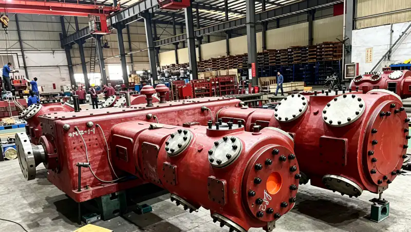
Rekodkan suhu sedutan, setiap tekanan antara peringkat, nyahcas akhir dan nyahcas peringkat selepas penstabilan. Bandingkan corak dengan garis dasar pentauliahan pada beban yang serupa. Injap yang bocor sering mengganggu nisbah tekanan peringkat bersebelahan dan boleh meningkatkan suhu silinder atau nyahcas kerana gas dimampatkan semula berulang kali. Corak ini lebih bermaklumat daripada tekanan akhir sahaja.
Ikuti prosedur ujian injap pembekal pemampat. Bergantung pada reka bentuk, ini mungkin melibatkan perbandingan suhu, pemeriksaan pemunggahan terkawal, tingkah laku tekanan selepas penutupan atau pemeriksaan selepas pengasingan. Jangan longgarkan penutup injap pada mesin bertekanan. Jika injap ditanggalkan, periksa keadaan plat atau cincin, spring, tempat duduk, mendapan dan kerosakan yang menjelaskan kebocoran dan bukannya memasang elemen baharu tanpa pemeriksaan punca utama.
5. Kebocoran cincin berasingan, kebocoran pembungkusan dan kehilangan gas luaran
Tiupan omboh-cincin mengurangkan penghantaran silinder dan mungkin mengubah kelakuan kotak engkol, kepingan jarak atau bolong bergantung pada reka bentuk pemampat. Kebocoran pembungkusan lebih cenderung muncul sebagai aliran bolong yang meningkat dari kawasan pembungkusan rod. Atur ukuran bolong atau kebocoran yang ditetapkan dan bandingkannya dengan nilai sebelumnya. Kebocoran luaran pada bebibir, longkang, injap pelega, tiub atau kelengkapan penerima boleh menggunakan kapasiti tanpa mengubah keseimbangan peringkat dalaman dengan cara yang sama.
Gunakan pengesanan kebocoran yang diluluskan selepas memastikan kawasan tersebut selamat. Jika kebocoran cincin disyaki, gabungkan kehilangan prestasi dengan pemeriksaan silinder, keadaan cincin, keadaan lubang dan keseimbangan tekanan sebelum memutuskan skop baik pulih. Jika pembungkusan adalah sumbernya, periksa permukaan dan penjajaran rod serta elemen pembungkusan; menggantikan pengedap pada rod yang rosak boleh menyebabkan berulangnya kebocoran dengan cepat.
Gunakan laman web tersebut pemampat gas nitrogen sumber sebagai semakan kedua apabila menterjemahkan keperluan ini kepada spesifikasi pemampat. Semakan silang di sini berkaitan dengan mengapa pemampat nitrogen tidak mencapai tekanan nyahcas.
6. Betulkan punca utama dan buktikan pemulihan pada tugas asal
Pulihkan bekalan sedutan, keadaan kawalan, injap, gelang, pembungkusan, kebocoran atau permintaan hiliran seperti yang ditunjukkan oleh diagnosis. Pembaikan berbanding penggantian hendaklah mengikut ukuran haus, keadaan komponen, kriteria vendor dan kos intervensi berulang. Jangan meningkatkan titik set atau kelajuan pelepasan melebihi had yang diluluskan untuk menutup kapasiti yang hilang.
Selepas pembetulan, ulangi keadaan operasi yang sama yang digunakan untuk membuktikan kerosakan. Rekodkan tekanan sedutan, tekanan dan suhu peringkat, aliran, kelajuan, kenaikan tekanan penerima, kebocoran atau kelakuan bolong, dan permintaan hiliran. Pemulihan tekanan tanpa aliran yang sepadan masih boleh menyembunyikan masalah jika pengguna ditutup sementara; penerimaan harus menghasilkan semula tugas sebenar yang diperlukan.
Jadual diagnostik tekanan rendah
| Barang | Soalan kejuruteraan | Isyarat pengesahan atau keputusan |
|---|---|---|
| Pemeriksaan instrumen | Adakah tekanan pelepasan sebenarnya rendah pada titik kawalan yang ditetapkan? | Pengukuran bebas sepadan dengan instrumen yang dipasang. |
| Pemeriksaan bekalan | Adakah tekanan sedutan kekal stabil semasa dibebankan? | Tekanan masuk pemampat kekal berhampiran keadaan sumber yang dijangkakan. |
| Pemeriksaan dalaman | Peringkat manakah yang menyimpang daripada tekanan atau suhu asas? | Corak peringkat mengarahkan pemeriksaan ke arah injap, gelang atau kawalan. |
| Pemeriksaan permintaan | Adakah aliran yang dihantar mencukupi untuk pengguna yang terhubung dan kebocoran? | Tekanan pulih apabila permintaan sebenar berada dalam kapasiti pemampat yang disahkan. |
| Rekodkan asas akhir dalam RFQ, fail pentauliahan atau rekod penyelenggaraan supaya jurutera lain boleh menghasilkan semula keputusan tersebut. | ||
Lembaran kerja pengesahan projek
Tukarkan item semakan “sahkan bacaan” kepada langkah penerimaan yang direkodkan. Kenal pasti di mana tekanan pelepasan diperhatikan, keadaan operasi pada ketika itu dan keadaan hulu atau hiliran yang boleh mengubah kebocoran injap. Rekodkan instrumen, lukisan, helaian data atau pemeriksaan fizikal yang digunakan untuk menetapkan asas. Kemudian lakukan tindakan “Sahkan tekanan pelepasan dengan instrumen bebas di lokasi yang betul.” di bawah keadaan yang boleh diulang. Jika keputusan bercanggah dengan tingkah laku yang dijangkakan, tahan keputusan reka bentuk atau penyelenggaraan seterusnya sehingga percanggahan dijelaskan. Ini memberi jurutera lain konteks yang mencukupi untuk menghasilkan semula pemeriksaan tanpa bergantung pada ingatan atau andaian yang tidak didokumenkan.
Gunakan tekanan sedutan sebagai pusat pemeriksaan lapangan yang dikaitkan dengan "Rekod aliran sebenar dan asingkan permintaan hiliran yang tidak dijangka melalui prosedur yang diluluskan.". Tuliskan lokasi pengukuran atau pemeriksaan, keadaan gas, beban pemampat, kedudukan injap yang berkaitan dan dokumen yang mentakrifkan penerimaan. Periksa silang kebocoran gelang omboh pada masa yang sama supaya gejala tempatan tidak disalah anggap sebagai masalah keseluruhan sistem. Konsep "periksa bekalan sedutan" hanya lengkap apabila pemerhatian membawa kepada keputusan yang jelas: terima, betulkan atau sampaikan untuk semakan pembekal. Ulangi pemeriksaan selepas sebarang pembetulan dan simpan nilai sebelum dan selepas dengan rekod pentauliahan atau penyelenggaraan.
Sahkan "periksa pemunggah dan kawalan" dengan mewujudkan satu keadaan terkawal di mana kebocoran injap dan pemunggah boleh ditafsirkan bersama. Stabilkan sistem, catatkan tekanan, suhu, aliran atau keadaan mesin sebagai berkaitan dan gunakan instrumen yang dikalibrasi atau pemeriksaan langsung di lokasi yang dinamakan. Jalankan "Ukur tekanan dan suhu sedutan pada pemampat semasa dimuatkan." dan rekodkan tindak balas yang dijangkakan dan diperhatikan. Jika had khusus model diperlukan, dapatkannya daripada dokumentasi pemampat, bekas, paip, penjana atau proses yang dipilih dan bukannya memasukkan nilai generik. Rekod tersebut harus menunjukkan mengapa keputusan muktamad secara teknikalnya boleh dipertahankan.
Sebelum menutup arahan kerja, pastikan “Sahkan kelajuan sebenar, kedudukan pemunggah, injap kitar semula dan keadaan kawalan.” boleh dikesan kepada bukti. Untuk kebocoran gelang omboh, catatkan titik rujukan dan unit atau keadaan fizikal; untuk tolok tekanan, catatkan titik perbandingan yang mengesahkan sistem berfungsi secara koheren. Kaitkan kedua-dua pemerhatian dengan “injap ujian” dan dengan beban atau mod operasi sebenar. Nilai tanpa lokasi dan keadaan sukar untuk digunakan semula kemudian. Jika semakan mendedahkan ketidakpadanan, betulkan sekatan, keadaan kawalan, keadaan komponen atau andaian reka bentuk yang menyebabkannya, kemudian ulangi pemerhatian yang sama supaya pembaikan terbukti dan bukannya diandaikan.
Sebelum membekukan pilihan peralatan, bandingkan tugas ini dengan tugas tapak pemampat nitrogen perindustrian julat dan sahkan bahawa asas tekanan yang sama sedang digunakan. Semakan silang di sini berkaitan dengan mengapa pemampat nitrogen tidak mencapai tekanan nyahcas.
Anggap "nilai cincin dan pembungkusan" sebagai eksperimen pentauliahan kecil. Takrifkan keadaan permulaan, perhatikan pemunggah, ubah hanya pembolehubah yang diperlukan untuk ujian yang diluluskan dan perhatikan tindak balas dalam tekanan pelepasan. Tindakan "Bandingkan tekanan peringkat, suhu dan penunjuk kebocoran dengan data garis dasar." harus meninggalkan rekod keadaan awal, intervensi, keadaan akhir dan sebarang tindak balas penggera atau kawalan. Ini berguna apabila beberapa komponen boleh mewujudkan simptom yang sama. Dengan mengubah satu faktor pada satu masa dan memastikan pemampat berada di dalam sampul surat yang diluluskan, pasukan boleh memisahkan punca daripada kebetulan dan mengelakkan penggantian perkakasan yang tidak bertanggungjawab.
Sempadan keselamatan dan pengesahan
Penyelesaian masalah pemampat yang sedang berjalan melibatkan mesin berputar, permukaan panas, gas bertekanan tinggi dan risiko kekurangan oksigen. Buat pemerhatian luaran dari lokasi yang selamat dan gunakan instrumen jarak jauh jika boleh. Asingkan, kunci keluar, kurangkan tekanan dan sahkan tenaga sifar sebelum membuka injap, silinder, bekas pembungkusan, penapis atau paip. Jangan sekali-kali meningkatkan kelajuan, tekanan atau tetapan pelantik di luar had pengeluar untuk memaksa mesin mencapai tekanan sasaran.
Diagnosis tekanan rendah langkah demi langkah
- Sahkan tekanan pelepasan dengan instrumen bebas di lokasi yang betul.
- Rekod aliran sebenar dan asingkan permintaan hiliran yang tidak dijangka melalui prosedur yang diluluskan.
- Ukur tekanan dan suhu sedutan pada pemampat semasa dimuatkan.
- Sahkan kelajuan sebenar, kedudukan pemunggah, injap kitar semula dan keadaan kawalan.
- Bandingkan tekanan peringkat, suhu dan penunjuk kebocoran dengan data asas.
- Baiki punca yang disahkan dan ulangi ujian beban asal untuk membuktikan pemulihan.
Soalan tekanan pelepasan
Mengapakah tekanan boleh rendah sedangkan aliran pemampat kelihatan normal?
Permintaan mungkin melebihi aliran, kebocoran hiliran mungkin menggunakan inventori, atau tekanan mungkin diukur selepas sekatan. Bandingkan aliran dan tekanan pada titik yang ditentukan di bawah keadaan operasi yang sama.
Adakah suhu peringkat tinggi membuktikan injap yang rosak?
Tidak. Nisbah mampatan yang tinggi, penyejukan yang lemah, gas sedutan panas dan kebocoran injap semuanya boleh meningkatkan suhu. Gunakan corak tekanan peringkat dan ujian pengesahan yang diluluskan sebelum menggantikan injap.
Perlukah saya meningkatkan kelajuan pemampat untuk memulihkan tekanan?
Hanya dalam lingkungan operasi yang diluluskan dan hanya selepas mengesahkan bahawa sistem direka bentuk untuk tindak balas kawalan tersebut. Kelajuan tidak boleh digunakan untuk menyembunyikan sekatan sedutan, kebocoran atau haus mekanikal.
Peraturan diagnostik
Diagnosis tekanan nyahcas rendah dari luar ke dalam: buktikan instrumen dan permintaan, lindungi keadaan sedutan, sahkan kawalan dan kelajuan, kemudian gunakan data peringkat untuk menguji injap, gelang, pembungkusan dan kebocoran. Pembaikan hanya selesai apabila pemampat menghasilkan semula tekanan dan aliran yang diperlukan pada keadaan operasi asal.

























