विवरण
3ZW-9.5/30 नाइट्रोजन कंप्रेसर – 3.00 MPa उच्च दबाव प्रक्रिया अनुप्रयोगों के लिए तीन-चरण वाला तेल-मुक्त N2 बूस्टर
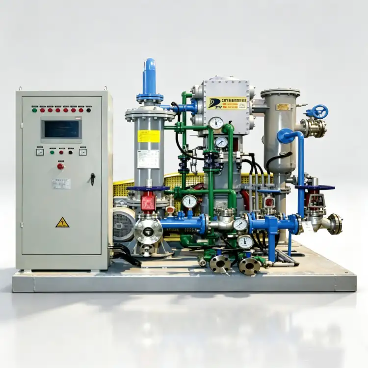
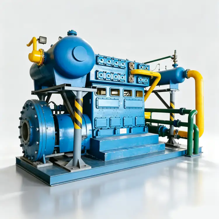
3.00 MPa डिस्चार्ज प्रेशर पर 9.5 m³/min की क्षमता से निर्मित, 3ZW-9.5/30 एक तीन-चरण, तीन-पंक्ति वाला तेल-मुक्त पिस्टन नाइट्रोजन कंप्रेसर है जिसे अति-उच्च दबाव वाले नाइट्रोजन इंजेक्शन, गैस सिलेंडर फिलिंग स्टेशनों और जटिल रासायनिक प्रक्रिया अनुप्रयोगों के लिए डिज़ाइन किया गया है। इसमें तेल का कोई संदूषण नहीं होता, बहु-चरणीय थर्मोडायनामिक अनुकूलन है और यह अत्यधिक दबाव पर निरंतर संचालन के लिए निर्मित है।
उत्पाद अवलोकन
The 3ZW-9.5/30 नाइट्रोजन कंप्रेसर यह हमारी ऑयल-फ्री पिस्टन कंप्रेसर तकनीक का शिखर है, जिसे विशेष रूप से उन अनुप्रयोगों के लिए डिज़ाइन किया गया है जिनमें पर्याप्त प्रवाह क्षमता और अति-उच्च डिस्चार्ज दबाव दोनों की आवश्यकता होती है। इसकी रेटेड क्षमता है... 9.5 घन मीटर/मिनट और एक असाधारण 3.00 एमपीए डिस्चार्ज दबावयह इकाई हमारे औद्योगिक नाइट्रोजन कंप्रेसर पोर्टफोलियो के उच्च दबाव वाले सेगमेंट में आती है, जो रासायनिक संश्लेषण, गैस सिलेंडर भरने और उच्च दबाव वाले निष्क्रियकरण कार्यों में सबसे कठिन प्रक्रिया आवश्यकताओं को पूरा करती है।
3ZW-9.5/30 को पारंपरिक विकल्पों से अलग करने वाली बात यह है कि इसमें तीन-चरणीय संपीड़न वास्तुकला पूरी तरह से तेल-मुक्त संपीड़न मार्ग के साथ संयुक्त। तीनों चरणों में पिस्टन रिंग और राइडर बैंड उन्नत स्व-चिकनाई वाले PTFE मिश्रित पदार्थों से सटीक रूप से मशीनीकृत होते हैं जो हाइड्रोकार्बन स्नेहक के बिना काम करते हैं। यह अंतर्निहित तेल-मुक्त विशेषता सुनिश्चित करती है कि नाइट्रोजन प्रवाह पूरी तरह से शुद्ध रहे, जिससे आईएसओ 8573-1 क्लास 0 प्रमाणन स्वाभाविक रूप से। फार्मास्युटिकल विनिर्माण, इलेक्ट्रॉनिक्स निर्माण और खाद्य-ग्रेड गैस उत्पादन में लगे ऑपरेटरों के लिए, यह डाउनस्ट्रीम तेल-निष्कासन निस्पंदन प्रणालियों के पूंजीगत व्यय और निरंतर रखरखाव के बोझ को समाप्त करता है जो चिकनाई युक्त विकल्पों के साथ अनिवार्य होगा।
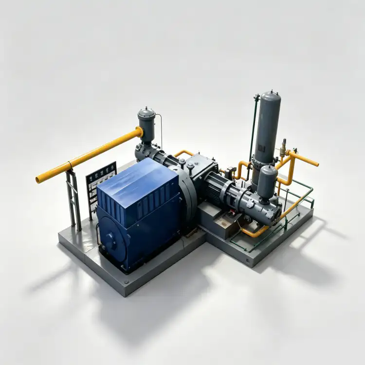
कंप्रेसर में एक तीन-चरण, तीन-पंक्ति (三列三级) यह विन्यास थर्मोडायनामिक रूप से आवश्यक है ताकि सामान्य इनलेट स्थितियों से 3.00 MPa का डिस्चार्ज दबाव प्राप्त किया जा सके। लगभग 30:1 से 60:1 का समग्र दबाव अनुपात तीन संपीड़न सिलेंडरों में वितरित किया जाता है, जिसमें प्रत्येक चरण एक प्रबंधनीय दबाव अनुपात पर संचालित होता है। चरणों के बीच स्वतंत्र इंटरकूलर संपीड़न की पर्याप्त ऊष्मा को दूर करते हैं, जिससे डिस्चार्ज तापमान सुरक्षित परिचालन सीमाओं के भीतर बना रहता है और PTFE सीलिंग तत्वों की अखंडता संरक्षित रहती है। मजबूत कच्चा लोहा फ्रेम और गतिशील रूप से संतुलित जाली स्टील क्रैंकशाफ्ट न्यूनतम सेवा जीवन के लिए उपयुक्त हैं। 120,000 घंटे मानक रखरखाव प्रोटोकॉल के तहत।
तकनीकी विशिष्टताएँ – 3ZW-9.5/30
| पैरामीटर | कीमत | इकाई |
|---|---|---|
| नमूना | 3ZW-9.5/30 | – |
| नमूना | तीन-चरण, तीन-पंक्ति (三列三级) | – |
| क्षमता | 9.5 | m³/min |
| डिस्चार्ज दबाव | 3.00 | एमपीए |
| कंप्रेसर का आकार (लंबाई × चौड़ाई × ऊंचाई) | 1845 × 1660 × 2360 | मिमी |
| वज़न | 3.50 | टी |
| शक्ति | 110 | किलोवाट |
| वोल्टेज | 380 | वी |
| गैस माध्यम | नाइट्रोजन (N₂) | – |
| स्नेहन | बिना तेल का | – |
* सभी विनिर्देश मानक संदर्भ स्थितियों (ISO 1217, अनुलग्नक C) के आधार पर निर्धारित किए गए हैं। वास्तविक प्रदर्शन स्थल की ऊंचाई, परिवेश के तापमान और इनलेट स्थितियों के आधार पर भिन्न हो सकता है।
मुख्य विशेषताएं और इंजीनियरिंग संबंधी लाभ
1. अति उच्च दबाव के लिए तीन-चरणीय संपीड़न
3ZW-9.5/30 में निम्नलिखित का उपयोग किया गया है: तीन-चरणीय संपीड़न वास्तुकला वायुमंडलीय या कम दबाव वाली इनलेट स्थितियों से 3.00 MPa का डिस्चार्ज दबाव प्राप्त करने के लिए यह ऊष्मागतिकीय रूप से आवश्यक है। कुल दबाव अनुपात तीन संपीड़न सिलेंडरों—कम दबाव, मध्यम दबाव और उच्च दबाव—में वितरित होता है, जिनमें से प्रत्येक लगभग 3:1 से 4:1 के दबाव अनुपात पर संचालित होता है। यह चरणबद्ध दृष्टिकोण प्रत्येक चरण के डिस्चार्ज तापमान को 155°C से नीचे सीमित करता है, जिससे PTFE सीलिंग तत्वों का तापीय क्षरण रोका जा सकता है और समान दबाव अनुपात प्राप्त करने वाले दो-चरणीय डिज़ाइनों की तुलना में वाल्व प्लेट का जीवनकाल लगभग 50% तक बढ़ जाता है। चरणों के बीच स्थित दो स्वतंत्र इंटरकूलर संपीड़न की ऊष्मा को दूर करते हैं, जिससे संपीड़न पथ के दौरान इष्टतम ऊष्मागतिकीय दक्षता बनी रहती है।
2. उच्च दबाव वाली सेवाओं के लिए उन्नत तेल-मुक्त पीटीएफई सीलिंग
तीनों संपीड़न चरणों में एक विशेष तकनीक का उपयोग किया जाता है। स्व-चिकनाई वाले पिस्टन रिंग और राइडर बैंड असेंबली उच्च घनत्व वाले PTFE कंपोजिट से निर्मित, जिसमें ग्लास फाइबर और कांस्य कणों का उपयोग किया गया है। यह सामग्री बिना किसी बाहरी हाइड्रोकार्बन स्नेहन के 0.06 से कम घर्षण गुणांक प्राप्त करती है। 3.00 MPa के डिस्चार्ज दबाव पर, तेल वाष्प का आंशिक दबाव 0.30 MPa की तुलना में लगभग 10 गुना अधिक होगा, जिससे तेल संदूषण की समस्या कई गुना बढ़ जाएगी। तेल-मुक्त डिज़ाइन निम्नलिखित लाभ प्राप्त करता है: ISO 8573-1 क्लास 0 प्रमाणन मूल रूप सेइससे लुब्रिकेटेड विकल्पों के साथ अनिवार्य रूप से आवश्यक डाउनस्ट्रीम कोलेसिंग फिल्टर, एक्टिवेटेड कार्बन एडसॉर्बर और ऑयल मॉनिटरिंग इंस्ट्रूमेंटेशन की आवश्यकता समाप्त हो जाती है। PTFE फॉर्मूलेशन को विशेष रूप से 185°C तक के तापमान पर निरंतर संचालन के लिए डिज़ाइन किया गया है, जो अति-उच्च दबाव संपीड़न के अत्यधिक तापीय तनाव के तहत विश्वसनीय सीलिंग अखंडता सुनिश्चित करता है।
3. तीन-पंक्ति बल-संतुलित फ्रेम डिजाइन
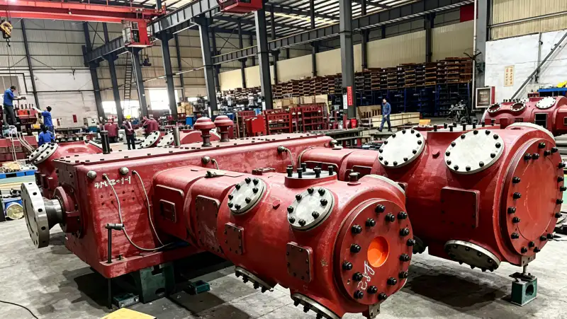
मुख्य ढांचा ढलाई द्वारा निर्मित होता है GG25 धूसर कच्चा लोहा (ASTM A48 क्लास 30B के समकक्ष) प्रबलित दीवार खंडों और अभिन्न शीतलन जल मार्गों के साथ। तीन-पंक्ति विपरीत-सिलेंडर व्यवस्था यह क्रैंकशाफ्ट पर क्रमिक बल निरस्तीकरण प्रदान करता है, जिसमें पहला और तीसरा सिलेंडर दूसरे सिलेंडर का विरोध करते हुए लगभग पूर्ण प्रथम-क्रम बल संतुलन प्राप्त करते हैं। यह यांत्रिक परिष्कार समान क्षमता वाले एकल-पंक्ति डिज़ाइनों की तुलना में नींव पर संचारित असंतुलित जड़त्व बलों को 85% से अधिक कम कर देता है। परिणामस्वरूप, एक असाधारण रूप से सुचारू रूप से चलने वाला उच्च-दबाव कंप्रेसर प्राप्त होता है जो उच्च-दबाव प्रत्यावर्ती मशीनों के लिए आमतौर पर आवश्यक भारी जड़त्व अवरोधों के बिना एक मानक प्रबलित कंक्रीट पैड पर संचालित हो सकता है।
4. उच्च दक्षता वाला मानक 380V ड्राइव
3ZW-9.5/30 एक द्वारा संचालित है 110 किलोवाट, 380 वोल्ट, 50 हर्ट्ज़ त्रि-चरण प्रेरण मोटर यह IEC 60034-1 दक्षता वर्ग IE3 के अनुरूप है। तीन-चरण संपीड़न के लिए पर्याप्त बिजली की आवश्यकता के बावजूद, मानक कम-वोल्टेज कॉन्फ़िगरेशन को मध्यम-वोल्टेज स्विचगियर की आवश्यकता के बिना मौजूदा 380V औद्योगिक वितरण पैनलों में सीधे एकीकृत किया जा सकता है। इस विद्युत सुगमता के कारण 3ZW-9.5/30 छोटे गैस फिलिंग स्टेशनों से लेकर मध्यम आकार के रासायनिक संयंत्रों तक, औद्योगिक सुविधाओं की एक विस्तृत श्रृंखला के लिए विद्युत अवसंरचना उन्नयन की आवश्यकता के बिना उपलब्ध है।
अनुप्रयोग परिदृश्य
उच्च दाब वाले नाइट्रोजन सिलेंडर भरने के स्टेशन
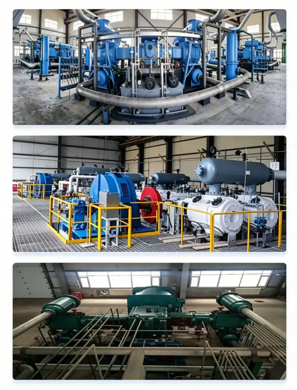
3ZW-9.5/30 विशेष रूप से इसके लिए बनाया गया है नाइट्रोजन सिलेंडर भरने की प्रक्रियाएँ जहां गैस को मानक औद्योगिक गैस सिलेंडरों के लिए आवश्यक 15-20 एमपीए दबाव तक संपीड़ित करना होता है। हालांकि कंप्रेसर का 3.00 एमपीए डिस्चार्ज दबाव सीधे अंतिम सिलेंडर भरने के दबाव तक नहीं पहुंचता है, यह एक अत्यधिक कुशल प्राथमिक बूस्टर के रूप में कार्य करता है जो डाउनस्ट्रीम उच्च-दबाव भरने वाले कंप्रेसरों के लिए आवश्यक संपीड़न अनुपात को काफी कम कर देता है। तीन-चरण डिजाइन सिलेंडर भरने के लिए विशेष रूप से फायदेमंद है क्योंकि यह एक स्थिर, ठंडा मध्यवर्ती दबाव प्रदान करता है जो अंतिम उच्च-दबाव चरण की दक्षता और दीर्घायु में सुधार करता है। सिलेंडर भरने के लिए तेल-मुक्त प्रमाणन अनिवार्य है क्योंकि किसी भी प्रकार का तेल संदूषण सिलेंडरों में फंस जाएगा और अंतिम उपयोगकर्ताओं तक पहुंच जाएगा, जिससे स्वास्थ्य सेवा, इलेक्ट्रॉनिक्स और खाद्य अनुप्रयोगों में महत्वपूर्ण प्रक्रियाओं को संभावित रूप से नुकसान पहुंच सकता है।
रासायनिक संश्लेषण और उच्च दाब रिएक्टर निष्क्रियकरण
रासायनिक प्रक्रिया संयंत्रों में, 3ZW-9.5/30 नाइट्रोजन कंप्रेसर अति उच्च दबाव वाली नाइट्रोजन प्रदान करता है उच्च दाब रिएक्टर निष्क्रियकरण, उत्प्रेरक बिस्तर संरक्षण और अतिक्रांतिक द्रव निष्कर्षण प्रक्रियाएँ3.00 एमपीए का डिस्चार्ज दबाव 2.5 एमपीए तक के दबाव पर संचालित होने वाले रिएक्टरों में निष्क्रिय वातावरण बनाए रखने के लिए पर्याप्त है, जिससे दबाव में उतार-चढ़ाव के दौरान भी पात्र में नाइट्रोजन का निरंतर प्रवाह सुनिश्चित होता है। तीन-चरणीय डिज़ाइन उत्कृष्ट दबाव स्थिरता प्रदान करता है, जो उन रासायनिक प्रक्रियाओं के लिए महत्वपूर्ण है जहां नाइट्रोजन दबाव में उतार-चढ़ाव प्रतिक्रिया गतिकी या उत्पाद की गुणवत्ता को प्रभावित कर सकता है। तेल-मुक्त डिज़ाइन उत्प्रेरक विषाक्तता और उत्पाद संदूषण को रोकता है जो तेल की थोड़ी सी भी मात्रा के रिसाव से हो सकता है।
तेल और गैस पाइपलाइन दबाव परीक्षण
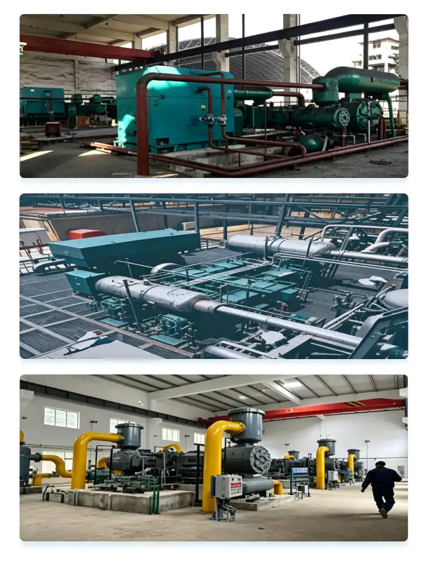
तेल और गैस उद्योग में, नाइट्रोजन पसंदीदा माध्यम है पाइपलाइनों, प्रेशर वेसल्स और वेलहेड उपकरणों का हाइड्रोस्टैटिक और न्यूमेटिक प्रेशर परीक्षण क्योंकि यह अक्रिय है और जल परीक्षण से जुड़े संक्षारण और संदूषण के जोखिमों से बचाता है। 3ZW-9.5/30 का 3.00 MPa का डिस्चार्ज प्रेशर API क्लास 600 (2.5 MPa वर्किंग प्रेशर) तक की पाइपलाइनों और उपकरणों के परीक्षण के लिए उपयुक्त है। तेल-मुक्त डिज़ाइन आवश्यक है क्योंकि परीक्षण नाइट्रोजन में किसी भी प्रकार के तेल संदूषण को पाइपलाइन संक्षारण उत्पादों या अवशिष्ट हाइड्रोकार्बन के रूप में गलत समझा जा सकता है, जिससे गलत परीक्षण परिणाम और महंगा पुनः परीक्षण हो सकता है। 9.5 m³/min की क्षमता बड़े व्यास की पाइपलाइनों को तेजी से दबावित करने की अनुमति देती है, जिससे परीक्षण चक्र का समय कम हो जाता है और परियोजना उत्पादकता में सुधार होता है।
इलेक्ट्रॉनिक्स के लिए अति उच्च-शुद्धता नाइट्रोजन आपूर्ति
सेमीकंडक्टर निर्माण सुविधाओं को उच्च दबाव पर नाइट्रोजन की आवश्यकता होती है। वेफर परिवहन प्रणाली का दबाव बढ़ाना, रासायनिक वाष्प जमाव (सीवीडी) कक्ष की सफाई करना और फोटोलिथोग्राफी उपकरणों को उच्च दबाव पर सुखाना।3ZW-9.5/30 का 3.00 MPa का डिस्चार्ज प्रेशर उच्च-वेग वाले नाइट्रोजन जेट को संचालित करता है, जिनका उपयोग सटीक सफाई और कण निष्कासन अनुप्रयोगों में किया जाता है। सेमीकंडक्टर निर्माण में तेल-मुक्त डिज़ाइन अत्यंत आवश्यक है, जहाँ नैनोमीटर-स्केल एकीकृत परिपथों में उप-ppb तेल संदूषण भी विनाशकारी दोष उत्पन्न कर सकता है। तीन-चरण संपीड़न असाधारण रूप से स्थिर डिस्चार्ज प्रेशर प्रदान करता है, जो जमाव और नक़्क़ाशी उपकरणों में निरंतर प्रक्रिया स्थितियों को बनाए रखने के लिए महत्वपूर्ण है।
सामग्री और निर्माण
3ZW-9.5/30 का निर्माण उच्च गुणवत्ता वाली सामग्रियों से किया गया है जिन्हें अति उच्च दबाव वाले नाइट्रोजन के अनुकूलता, तापीय प्रतिरोध और विस्तारित परिचालन जीवन के लिए चुना गया है:
| अवयव | सामग्री | विनिर्देश |
|---|---|---|
| सिलेंडर ब्लॉक (एलपी) | स्लेटी कच्चा लोहा | GG25 / HT250, मानक दीवार मोटाई |
| सिलेंडर ब्लॉक (एमपी) | स्लेटी कच्चा लोहा | GG25 / HT250, प्रबलित दीवार + रिबिंग |
| सिलेंडर ब्लॉक (एचपी) | स्लेटी कच्चा लोहा | GG25 / HT250, हेवी-ड्यूटी प्रबलित कास्टिंग |
| क्रैंकशाफ्ट | जाली मिश्र धातु इस्पात | 42CrMo4, Q&T, ISO 1940 G2.5 गतिशील रूप से संतुलित |
| पिस्टन रिंग (सभी चरणों के लिए) | पीटीएफई-ग्लास-कांस्य मिश्रित | उच्च दबाव के लिए उपयुक्त, स्व-चिकनाईयुक्त, अधिकतम 185°C तापमान तक। |
| राइडर बैंड | पीटीएफई कंपोजिट | पिस्टन मार्गदर्शन, खरोंच रोधी, घिसाव दर <0.04 मिमी/1000 घंटे |
| वाल्व प्लेटें | स्टेनलेस स्टील | SS316, उच्च दबाव संकेंद्रित वलय स्प्रिंग डिजाइन |
| इंटरकूलर (2 यूनिट) | कार्बन स्टील शेल / SS316 ट्यूब | ASME VIII डिविजन 1, 1.5× हाइड्रोटेस्ट, 30 मिनट होल्ड |
| आफ्टरकूलर | कार्बन स्टील शेल / SS316 ट्यूब | उच्च दाब वाली फिन्ड ट्यूब, 32°C ठंडा पानी |
| उच्च दबाव पाइपिंग | सीमलेस स्टेनलेस स्टील | SS316, ANSI क्लास 900 फ्लैंज |
सभी दबाव सहन करने वाले घटकों को सख्त मानकों के अनुसार डिजाइन और निर्मित किया जाता है। एएसएमई बीपीवीसी सेक्शन आठवीं डिवीजन 1 या चीनी जीबी 150 मानकों के अनुसार। प्रत्येक वेल्ड जोड़ का एएसएमई खंड V, अनुच्छेद 2 के अनुसार 100% रेडियोग्राफिक निरीक्षण (आरटी) किया जाता है, और प्रत्येक पूर्ण दबाव पात्र को अधिकतम अनुमेय कार्यशील दबाव (एमएडब्ल्यूपी) के 1.5 गुना पर न्यूनतम 30 मिनट की अवधि के लिए हाइड्रोस्टैटिक दबाव परीक्षण के अधीन किया जाता है। उच्च दबाव पाइपिंग सिस्टम को 3.00 एमपीए परिचालन दबाव पर रिसाव-रोधी अखंडता सुनिश्चित करने के लिए एएनएसआई क्लास 900 फ्लैंग्ड कनेक्शन के साथ निर्बाध एसएस316 से निर्मित किया जाता है।
स्थापना एवं रखरखाव संबंधी दिशानिर्देश
नींव और संरचनात्मक आवश्यकताएँ
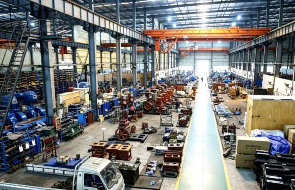
3ZW-9.5/30 का शुष्क भार 3.50 टन है और इसका गुरुत्वाकर्षण केंद्र बेसप्लेट से लगभग 850 मिमी ऊपर है। तीन-चरण उच्च-दबाव संचालन के बावजूद, तीन-पंक्ति विपरीत-सिलेंडर डिज़ाइन उत्कृष्ट बल संतुलन प्राप्त करता है, जिससे इसे किसी भी सतह पर स्थापित करना संभव हो जाता है। 6-8 टन के प्रबलित कंक्रीट जड़त्वीय ब्लॉकब्लॉक को इलास्टोमेरिक वाइब्रेशन आइसोलेटर (प्राकृतिक आवृत्ति 7–10 हर्ट्ज़) पर लगाया जाना चाहिए। न्यूनतम क्लीयरेंस आवश्यकताएँ: वाल्व तक पहुँच के लिए नॉन-ड्राइव साइड पर 1.2 मीटर, मोटर रखरखाव के लिए ड्राइव साइड पर 1.0 मीटर और क्रेन पहुँच के लिए ऊपर की ओर 1.5 मीटर। उच्च दबाव वाले डिस्चार्ज पाइपिंग (3.00 एमपीए) को कंपन से होने वाली थकान को रोकने और कर्मियों की सुरक्षा सुनिश्चित करने के लिए सपोर्ट और एंकरिंग पर विशेष ध्यान देने की आवश्यकता है।
शीतलन जल प्रणाली डिजाइन
शीतलन जल की मांग लगभग है 22 घन मीटर/घंटा प्रवेश तापमान 32°C से अधिक नहीं होना चाहिए। जल वितरण परिपथ तीन सिलेंडर जैकेट परिपथों और दो इंटरकूलरों को समानांतर/श्रृंखला हाइब्रिड व्यवस्था में जल की आपूर्ति करता है, जिसे तापीय प्रबंधन के लिए अनुकूलित किया गया है। अत्यधिक दबाव अनुपात को देखते हुए, दोनों इंटरकूलर पीटीएफई रिंग की अखंडता को बनाए रखने के लिए महत्वपूर्ण हैं और इन्हें हर समय पर्याप्त शीतलन जल प्रवाह प्राप्त होना चाहिए। जल गुणवत्ता विनिर्देश: पीएच 6.5–8.5, कुल घुलित ठोस < 500 मिलीग्राम/लीटर, क्लोराइड की मात्रा < 50 मिलीग्राम/लीटर (एसएस316 ट्यूब के क्षरण को रोकने के लिए), निलंबित ठोस < 30 मिलीग्राम/लीटर, और कुल कठोरता < 300 मिलीग्राम/लीटर (CaCO₃ के रूप में)। साइड-स्ट्रीम निस्पंदन के साथ एक बंद-लूप शीतलन टॉवर की पुरजोर अनुशंसा की जाती है।
निवारक रखरखाव अनुसूची
| अंतराल | सेवा मद | कार्रवाई आवश्यक है |
|---|---|---|
| दैनिक | परिचालन निरीक्षण | कंपन, असामान्य शोर, शीतलन जल प्रवाह, सभी चरणों के डिस्चार्ज दबाव और तापमान की जाँच करें। |
| 250 घंटे | वाल्व प्लेट निरीक्षण (सभी चरण) | कार्बन जमाव, स्प्रिंग की कमजोरी और दरारों के लिए सभी सक्शन/डिस्चार्ज वाल्वों को हटाकर उनकी जांच करें। |
| 1,000 घंटे | पिस्टन रिंग घिसाव आकलन (सभी चरण) | सभी चरणों पर ग्रूव क्लीयरेंस मापें; यदि क्लीयरेंस 0.18 मिमी से अधिक हो तो रिंग बदल दें। |
| 3,000 घंटे | मध्यवर्ती ओवरहाल | तीनों चरणों के सभी पिस्टन रिंग, राइडर बैंड और वाल्व प्लेट असेंबली को बदलें। |
| 6,000 घंटे | प्रमुख सुधार | क्रैंकशाफ्ट जर्नल की जांच करें, सभी बेयरिंग क्लीयरेंस को मापें, यदि क्लीयरेंस 0.08 मिमी से अधिक हो तो बेयरिंग बदलें। |
3ZW-9.5/30 का तेल-मुक्त डिज़ाइन, चिकनाई युक्त विकल्पों की तुलना में रखरखाव को काफी सरल बनाता है। इसमें तेल बदलने, तेल विश्लेषण करने, फ़िल्टर बदलने और सेपरेटर कार्ट्रिज बदलने की आवश्यकता नहीं होती है। मुख्य उपभोज्य घिसाव वाले पुर्जे हैं... पीटीएफई पिस्टन रिंग और राइडर बैंडये वाल्व आमतौर पर स्वच्छ नाइट्रोजन की स्थिति में 3,000-5,000 घंटे का सेवा जीवन प्राप्त करते हैं। तीसरे चरण में उच्च दबाव वाले वाल्व प्लेटों को 3.00 एमपीए पर अत्यधिक यांत्रिक तनाव के कारण अधिक बार निरीक्षण (हर 2,000 घंटे) की आवश्यकता हो सकती है, लेकिन कुल रखरखाव का बोझ तेल-चिकनाई वाले सिस्टम की तुलना में काफी कम रहता है।

अनुपालन एवं सुरक्षा प्रमाणपत्र
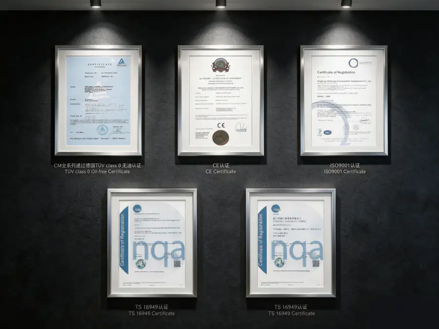
3ZW-9.5/30 नाइट्रोजन कंप्रेसर को निम्नलिखित अंतरराष्ट्रीय मानकों और नियामक ढांचों को पूरा करने या उससे आगे निकलने के लिए डिजाइन, निर्मित और परीक्षण किया गया है:
एएसएमई बीपीवीसी सेक्शन VIII Div.1, जीबी 150-2011, पीईडी 2014/68/ईयू मॉड्यूल ए
आईईसी 60034-1 (IE3 दक्षता), आईईसी 60204-1, आईएसओ 12100 मशीनरी सुरक्षा
ISO 8573-1 क्लास 0 (तेल की मात्रा), TÜV राइनलैंड द्वारा स्वतंत्र रूप से परीक्षित
आईएसओ 9001:2015, आईएसओ 14001:2015
नाइट्रोजन को साधारण दम घोंटने वाली गैस के रूप में वर्गीकृत किया गया है। 3.00 MPa के डिस्चार्ज दबाव पर, गैस के तेजी से निकलने और ऑक्सीजन के विस्थापन का खतरा अत्यधिक बढ़ जाता है। सभी 3ZW-9.5/30 इंस्टॉलेशन में कंप्रेसर रूम और आसपास के सभी क्षेत्रों में ऑक्सीजन की कमी की निरंतर निगरानी की व्यवस्था होनी चाहिए। उच्च दबाव वाले डिस्चार्ज पाइप में 110% (MAWP) रेटिंग वाले प्रेशर रिलीफ वाल्व और द्वितीयक सुरक्षा के रूप में रप्चर डिस्क लगे होने चाहिए। पाइप फटने की स्थिति में कर्मियों को गैस के छींटों से बचाने के लिए सभी उच्च दबाव वाले पाइप को सुरक्षित या ढका होना चाहिए। वेंटिलेशन सिस्टम को OSHA 29 CFR 1910.146 के अनुसार परिवेशी ऑक्सीजन का स्तर 19.5% से ऊपर बनाए रखना चाहिए। आपातकालीन शटडाउन इंटरलॉक 19.5% O₂ (अलार्म) पर सक्रिय होने चाहिए और 18.0% O₂ (हार्ड शटडाउन) पर स्वचालित आइसोलेशन शुरू कर देना चाहिए। इस उपकरण को संचालित या रखरखाव करने से पहले कर्मियों को अति-उच्च दबाव वाली गैस सुरक्षा प्रोटोकॉल में प्रशिक्षित किया जाना चाहिए। सभी रखरखाव गतिविधियों के लिए लॉक-आउट/टैग-आउट प्रक्रियाएं अनिवार्य हैं।
प्रदर्शन और दक्षता विश्लेषण
3ZW-9.5/30 एक उपलब्धि हासिल करता है लगभग 11.58 किलोवाट प्रति वर्ग मीटर/मिनट की विशिष्ट विद्युत खपत। 3.00 MPa डिस्चार्ज प्रेशर पर नाइट्रोजन की आपूर्ति की जाती है। यह विशिष्ट शक्ति आंकड़ा तीन चरणों के माध्यम से अति-उच्च दबाव संपीड़न की थर्मोडायनामिक वास्तविकता को दर्शाता है। उच्च दबाव वाले तेल-मुक्त कंप्रेसर सेगमेंट (डिस्चार्ज प्रेशर >2.50 MPa) में, यह दक्षता प्रतिस्पर्धी है और डायाफ्राम कंप्रेसर की तुलना में काफी बेहतर है, जो तेल-मुक्त अति-उच्च दबाव सेवा के लिए प्राथमिक विकल्प हैं। तुलना के लिए, समान क्षमता और दबाव प्रदान करने वाला एक डायाफ्राम कंप्रेसर आमतौर पर 16-20 kW/m³/min ऊर्जा की खपत करेगा और पूंजीगत व्यय में 4-6 गुना अधिक खर्च करेगा।
8,000 घंटे के वार्षिक परिचालन कार्यक्रम में, डायफ्राम विकल्पों की तुलना में 3ZW-9.5/30 की दक्षता का लाभ लगभग प्राप्त होता है। प्रति वर्ष 340,000–530,000 किलोवाट-घंटे की ऊर्जा बचत$0.08/kWh की दर पर, यह प्रति वर्ष बिजली की लागत में प्रत्यक्ष कमी के रूप में $27,200–$42,400 का प्रतिनिधित्व करता है। हालाँकि, 3ZW-9.5/30 के चयन का प्राथमिक आर्थिक कारक आमतौर पर यह होता है कि उच्च क्षमता, मध्यम पूंजी लागत और प्राकृतिक तेल-मुक्त संचालन का संयोजन अन्य कंप्रेसर प्रौद्योगिकियों के साथ इस दबाव स्तर पर यह उपलब्धि हासिल करना असंभव है। अति उच्च दबाव वाले नाइट्रोजन संपीड़न के लिए स्वामित्व की कुल लागत तीन-चरण पिस्टन डिजाइन की तुलना मल्टी-डायाफ्राम सिस्टम से करने पर 10 साल के परिचालन जीवनकाल में अनुमानित 40-50% की कमी आती है।
तीन-चरण वाली डिज़ाइन एकल-चरण उच्च-दबाव कंप्रेसर की तुलना में बेहतर दबाव स्थिरता प्रदान करती है, जो उन प्रक्रिया अनुप्रयोगों के लिए महत्वपूर्ण है जहां दबाव में उतार-चढ़ाव उत्पाद की गुणवत्ता या प्रक्रिया सुरक्षा को प्रभावित कर सकता है। अंतर-चरण शीतलन यह सुनिश्चित करता है कि प्रत्येक चरण इष्टतम ऊष्मागतिक दक्षता पर संचालित हो, जिससे आवश्यक दबाव वृद्धि के लिए कुल बिजली की खपत कम से कम हो जाती है।
अनुकूलन और ओईएम क्षमताएं
हम 3ZW-9.5/30 को विशिष्ट साइट स्थितियों, एकीकरण आवश्यकताओं और अंतिम उपयोगकर्ता की विशिष्टताओं के अनुरूप बनाने के लिए व्यापक अनुकूलन विकल्प प्रदान करते हैं:
- स्किड-माउंटेड टर्नकी पैकेज: संरचनात्मक स्टील स्किड पर एकीकृत लिफ्टिंग लग्स और एंकर बोल्ट टेम्पलेट्स के साथ पहले से असेंबल किया हुआ कंप्रेसर, मोटर, तीन कूलर, इंस्ट्रूमेंटेशन और कंट्रोल पैनल। सभी प्रणालियों का फ़ैक्टरी पूर्व-परीक्षण कमीशनिंग समय को 60% तक कम कर देता है।
- खतरनाक क्षेत्र विन्यास: पेट्रोकेमिकल संयंत्रों के लिए ATEX ज़ोन 2 और IECEx मानकों के अनुरूप मोटर और विद्युत आवरण। एकीकृत गैस पहचान और स्वचालित वेंटिलेशन इंटरलॉक के साथ आपातकालीन अलगाव वाल्व।
- उन्नत प्रक्रिया नियंत्रण: 10 इंच के एचएमआई टचस्क्रीन, मॉडबस टीसीपी/आईपी या ओपीसी-यूए के माध्यम से रिमोट मॉनिटरिंग और निर्बाध डीसीएस/एससीएडीए एकीकरण के साथ वैकल्पिक सीमेंस एस7-1200 या एलन-ब्रैडली कॉम्पैक्टलॉजिक्स पीएलसी। स्वचालित चरण अनुक्रमण और आपातकालीन ब्लोडाउन सहित उच्च दबाव सुरक्षा इंटरलॉक।
- पर्यावरण संरक्षण: तटीय प्रतिष्ठानों के लिए C5-M समुद्री-ग्रेड कोटिंग्स; 55°C परिवेश के लिए उष्णकटिबंधीयकृत विद्युत घटक; IP54-रेटेड ध्वनिक आवरण जो 1 मीटर पर शोर को 85 dB(A) से घटाकर 72 dB(A) कर देते हैं।
- ओईएम और प्राइवेट लेबल: गैस उपकरण वितरकों और सिस्टम इंटीग्रेटर्स के लिए अनुकूलित पेंट रंग, ब्रांडेड नेमप्लेट और स्थानीयकृत दस्तावेज़।
अनुकूलित कॉन्फ़िगरेशन यहां से उपलब्ध हैं न्यूनतम मात्रा 1 इकाईइंजीनियरिंग संबंधी प्रस्ताव आमतौर पर 5-7 कार्य दिवसों के भीतर प्रस्तुत किए जाते हैं। मानक डिलीवरी समय 12-14 सप्ताह है; दोहराए गए ऑर्डर की डिलीवरी ऑर्डर की पुष्टि के बाद 8-10 सप्ताह में की जाती है।
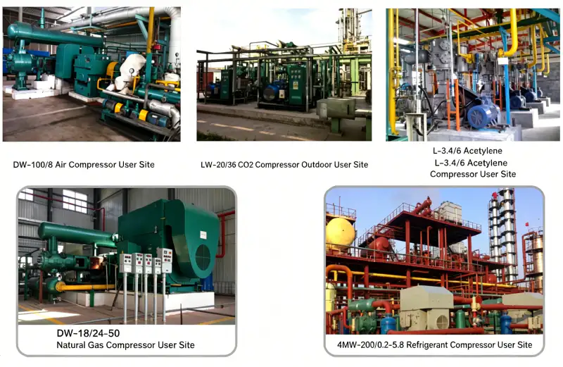
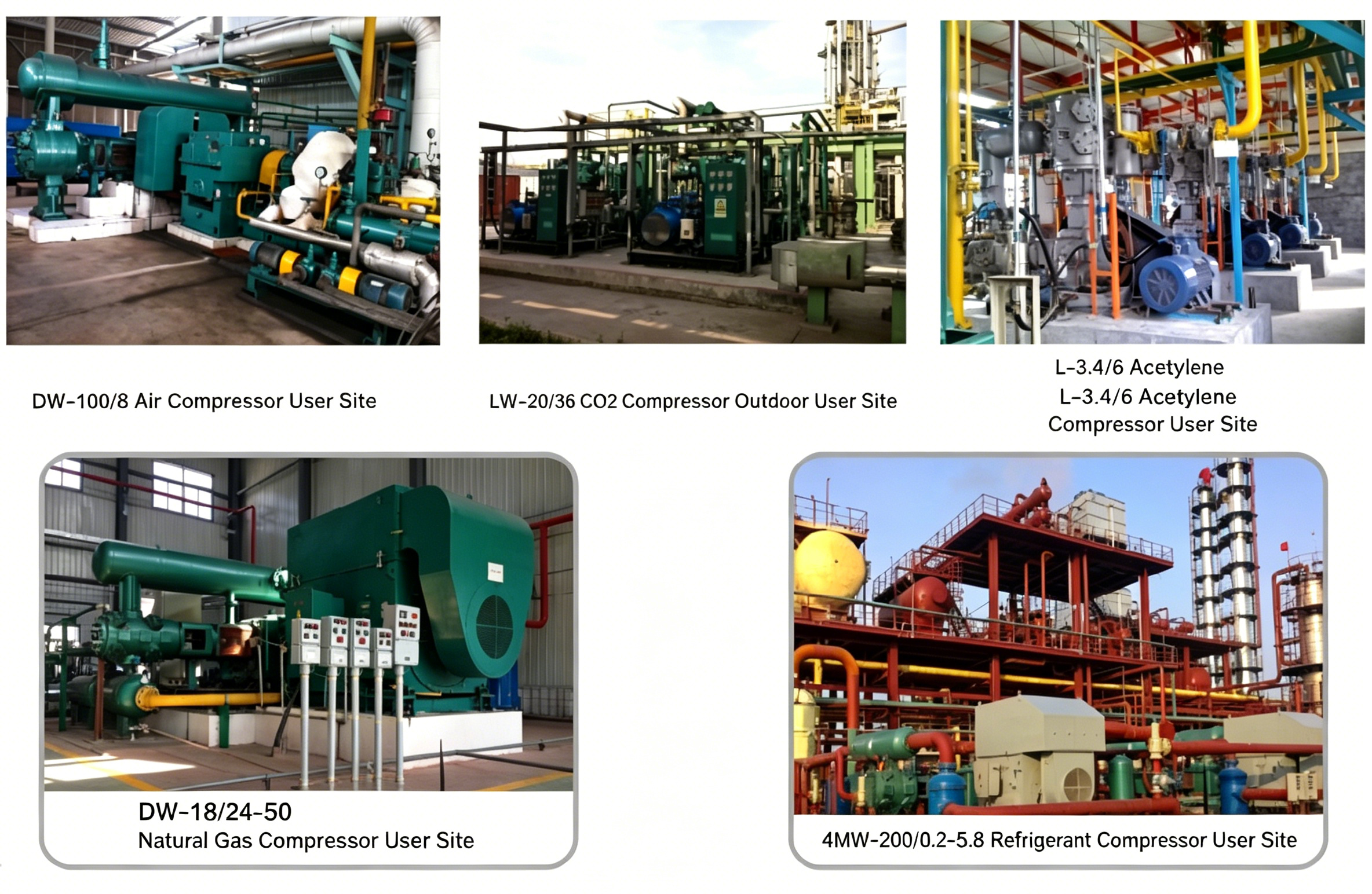
केस स्टडी: औद्योगिक गैस सिलेंडर फिलिंग स्टेशन का उन्नयन
ग्राहक: इंडोनेशिया में औद्योगिक गैस का एक प्रमुख वितरक जो विनिर्माण, स्वास्थ्य सेवा और इलेक्ट्रॉनिक्स क्षेत्रों को सेवाएं प्रदान करता है।
चुनौती: ग्राहक के मौजूदा सिलेंडर भरने के स्टेशन में एक तेल से चिकनाई युक्त दो-चरणीय कंप्रेसर का उपयोग किया जाता था, जो एक डायाफ्राम फिलिंग कंप्रेसर को ईंधन प्रदान करता था। प्राथमिक कंप्रेसर से तेल का संदूषण पूरे सिस्टम में फैल रहा था, जिसके कारण डायाफ्राम कंप्रेसर के अंतिम शुद्धिकरण बेड को डिज़ाइन किए गए 18 महीने के अंतराल के बजाय हर 4 महीने में बदलना पड़ रहा था। भरे हुए सिलेंडरों में तेल का स्तर 2.0 मिलीग्राम/मीटर³ तक पहुँच गया, जो चिकित्सा और इलेक्ट्रॉनिक्स-ग्रेड नाइट्रोजन के लिए निर्धारित 0.1 मिलीग्राम/मीटर³ विनिर्देश से अधिक था। तेल से दूषित हीट एक्सचेंजर के कारण डायाफ्राम कंप्रेसर की कार्यक्षमता भी कम हो गई थी।
समाधान: हमने आपूर्ति की 3ZW-9.5/30 तेल-मुक्त नाइट्रोजन कंप्रेसर प्राथमिक बूस्टर के रूप में, तेल-चिकनाई वाली इकाई को प्रतिस्थापित किया गया। तीन-चरण डिजाइन ने 3.00 एमपीए का स्थिर मध्यवर्ती दबाव प्रदान किया, जिससे डाउनस्ट्रीम डायाफ्राम कंप्रेसर की दक्षता में 15% का सुधार हुआ। तेल-मुक्त डिजाइन ने सक्रिय कार्बन शुद्धिकरण बेड की आवश्यकता को पूरी तरह से समाप्त कर दिया। इकाई को एकीकृत कूलर और रिमोट मॉनिटरिंग के साथ सीमेंस S7-1200 पीएलसी से युक्त एक कस्टम स्किड पर स्थापित किया गया था।
18 महीनों के बाद प्राप्त मात्रात्मक परिणाम:
- भरे हुए सिलेंडरों में नाइट्रोजन तेल की मात्रा: 2.0 मिलीग्राम/मी³ से घटकर <0.01 मिलीग्राम/मी³ हो गया।आईएसओ 8573-1 क्लास 0 का प्रमाणन प्राप्त किया।
- सक्रिय कार्बन बेड का प्रतिस्थापन: पूरी तरह से समाप्तजिससे उपभोग्य सामग्रियों पर प्रति वर्ष 18,000 रुपये की बचत होती है।
- डायाफ्राम कंप्रेसर की दक्षता: 15% द्वारा बेहतर बनाया गयाजिससे इसकी बिजली की खपत 22 किलोवाट कम हो जाती है।
- ग्राहक शिकायतें और वापसी: शून्य चालू होने के बाद से, अनुबंधों को 3 अतिरिक्त वर्षों के लिए नवीनीकृत किया गया है।
- वापसी की अवधि: 2.3 वर्ष लागत बचत और अनुबंध नवीनीकरण के आधार पर
“3ZW-9.5/30 ने हमारे फिलिंग स्टेशन को पूरी तरह से बदल दिया है। तेल-मुक्त डिज़ाइन ने हमारी गुणवत्ता नियंत्रण संबंधी समस्याओं को रातोंरात खत्म कर दिया है, और तीन-चरण संपीड़न ने हमारे डाउनस्ट्रीम उपकरणों को पहले से कहीं अधिक कुशलता से चलाने में सक्षम बना दिया है। हमारे चिकित्सा गैस ग्राहकों ने इस अंतर को तुरंत महसूस किया है।” — संचालन निदेशक, औद्योगिक गैस वितरक
अक्सर पूछे जाने वाले प्रश्न और चयन मार्गदर्शिका
संबंधित उत्पाद और समाधान
ZW सीरीज मल्टी-स्टेज ऑयल-फ्री कंप्रेसर
ऑक्सीजन, नाइट्रोजन, हाइड्रोजन और विशेष गैसों के लिए ऊर्ध्वाधर, बहु-चरणीय तेल-मुक्त कंप्रेसर। अति उच्च दबाव वाली गैस भरने और रासायनिक प्रक्रिया अनुप्रयोगों के लिए 9.00 एमपीए तक का डिस्चार्ज दबाव।
डीडब्ल्यू सीरीज हाई-प्रेशर नाइट्रोजन कंप्रेसर
0.40 MPa से 2.00 MPa तक के डिस्चार्ज दबाव के लिए डिज़ाइन की गई, DW श्रृंखला नाइट्रोजन इंजेक्शन, उच्च दबाव वाली पाइपलाइन बूस्टिंग और रासायनिक संश्लेषण को कवर करती है। क्षमता 2 से 130 m³/min तक है।
एलडब्ल्यू सीरीज के उच्च क्षमता वाले नाइट्रोजन कंप्रेसर
क्रायोजेनिक एएसयू बैकअप, वीपीएसए बूस्टिंग और औद्योगिक पाइपलाइन वितरण के लिए उच्च प्रवाह वाले तेल-मुक्त पिस्टन कंप्रेसर (20-130 m³/मिनट)। डिस्चार्ज दबाव 0.30 से 0.80 एमपीए तक।
हमारे बारे में विस्तृत जानकारी के लिए औद्योगिक नाइट्रोजन कंप्रेसर हमारे पोर्टफोलियो में तेल-मुक्त ऑक्सीजन कंप्रेसर, हाइड्रोजन कंप्रेसर, कार्बन डाइऑक्साइड कंप्रेसर और कस्टम-इंजीनियर्ड स्पेशलिटी गैस समाधान शामिल हैं। अधिक जानकारी के लिए, कृपया हमारी एप्लीकेशन इंजीनियरिंग टीम से संपर्क करें या हमारी ऑनलाइन उत्पाद सूची देखें।
क्या आप अपने अल्ट्रा-हाई-प्रेशर नाइट्रोजन सिस्टम को अपग्रेड करने के लिए तैयार हैं?
हमारे एप्लीकेशन इंजीनियर आपकी नाइट्रोजन प्रवाह आवश्यकताओं, सक्शन स्थितियों, डिस्चार्ज दबाव लक्ष्यों और एकीकरण संबंधी बाधाओं का मूल्यांकन करने के लिए तत्पर हैं। आपकी पूछताछ प्राप्त होने के 48 घंटों के भीतर हम निःशुल्क तकनीकी प्रस्ताव, फाउंडेशन लेआउट ड्राइंग, पाइपिंग और इंस्ट्रूमेंटेशन डायग्राम (P&ID) और स्वामित्व की कुल लागत (TCO) का विस्तृत विश्लेषण प्रदान करते हैं।
ईमेल: [email protected] 24 घंटों के भीतर जवाब