
Package boundaries change installation risk and future flexibility
A skid-mounted system can reduce field assembly, while a separated layout can improve access and site integration; the better choice depends on logistics and lifecycle needs.
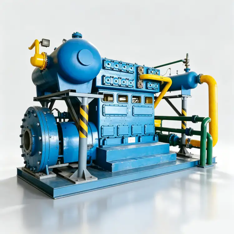
Skid-mounted and separately installed nitrogen compressor systems can use the same core compressor but create very different project work. A packaged skid may arrive with the compressor, motor, coolers, separators, instruments, valves, local controls and much of the interconnecting piping already assembled and tested. That can reduce field labor and simplify interface responsibility. A separate layout gives the plant more freedom to locate coolers, receivers, control panels or treatment equipment around existing structures and can improve access for large maintenance lifts. The tradeoff is more site piping, supports, cabling, alignment and coordination among contractors. The choice should be made by tracing the project from fabrication through transport, installation, operation and overhaul. Check the largest transport envelope, lifting plan, foundation loads, local pipe stress, ventilation, hazardous-area boundaries and the path required to remove valves, cylinders, motors or coolers. A compact skid is not automatically easier if it cannot pass through the plant or leaves no service clearance; a field-built arrangement is not automatically flexible if it creates dozens of poorly defined interfaces.

Layout terms to define before the GA drawing
- skid-mounted package
- A compressor system assembled on a common base with a defined factory scope of piping, instruments, coolers and controls.
- field-mounted equipment
- Compressor components or auxiliaries installed on separate foundations or structures and connected mainly at site.
- piping interfaces
- The suction, discharge, cooling, drain, vent and utility connections that cross the package boundary.
- foundation load
- Static and dynamic loads transferred from compressor, motor, skid and piping into the supporting structure.
- service access
- Space and lifting routes needed to inspect, remove and reinstall wear parts or major components.
- transport envelope
- The maximum packaged dimensions, weight, lifting points and route restrictions that govern delivery to the final location.
1. A skid reduces field interfaces when the scope is genuinely complete
The biggest skid advantage is controlled factory assembly. Pipe spools, instruments, guards and wiring can be installed around the compressor with repeatable workmanship, and more of the package can be inspected before shipment. This only helps if the vendor scope is clear. A “skid package” that excludes suction filtration, final cooler, receiver, control panel or critical valves may still leave significant field work. Create a battery-limit drawing that shows every mechanical, electrical and control connection. The goal is to move complexity from the construction site into a controlled fabrication environment, not merely to mount the compressor on steel and call it packaged.
2. Separate layouts can solve real space and maintenance problems
Existing plants rarely provide a clean rectangular area around the compressor. A water cooler may fit better near the cooling-water header, a receiver may need a different foundation, and a control panel may need to sit outside a hazardous or hot zone. Separating equipment can shorten utility runs or create better lifting access. It can also isolate heat sources and reduce congestion around valves and packing. The price is additional interconnecting pipe, supports, pressure drop and construction coordination. A layout review should consider the compressor throughout its life, including the largest component that might need removal, not only how neatly the new equipment fits on installation day.
When the process envelope is stable, the site’s nitrogen compressor skid page gives a practical equipment reference for the next selection step. The cross-check here is tied to skid-mounted separate nitrogen compressor systems layout better.
3. Transport and lifting can decide the issue before process engineering does
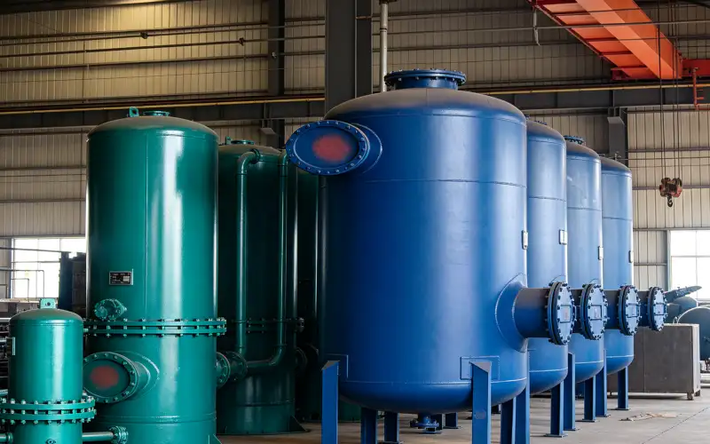
A fully assembled skid may be too wide, tall or heavy for the available road, plant gate, elevator, crane or indoor route. Breaking the package into modules can reduce shipping risk but creates field reconnection and alignment work. Ask for shipping dimensions and weights early, including temporary lifting frames. Check where the centre of gravity is and whether local lifting points are rated for the required assembly state. For overseas projects, containerization, preservation and reassembly should be included in the packaging plan. A compact machine is only useful if it can reach the foundation without unsafe improvisation.
4. Foundation and piping loads must be evaluated for the final arrangement
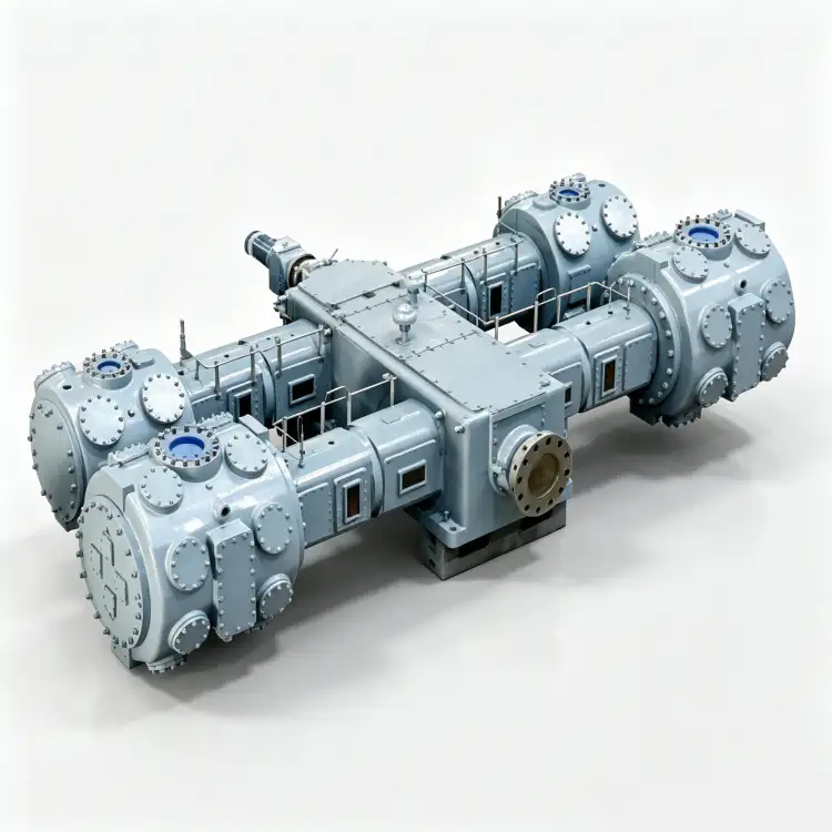
Reciprocating compressors generate dynamic forces and pulsating gas loads, so the base, foundation and connected piping require coordinated design. A common skid can help maintain alignment between compressor and motor, but the skid still needs appropriate support and anchorage. Separately mounted coolers or vessels create different nozzle loads and pipe support requirements. Flexible connectors should not be used as a substitute for correct alignment or pipe stress design. Ask the compressor supplier for allowable nozzle loads, dynamic information and foundation requirements for the selected configuration. Then make sure site piping does not pull the package out of alignment after it is bolted down.
5. Factory testing is easier on an integrated package, but site testing still matters
A skid can support more complete factory functional checks because instruments, valves and local controls are already installed. The project may be able to test logic, alarm functions, motor rotation provisions and portions of the piping before shipment. Site conditions still need to be proven after reconnection: actual cooling utility, suction pressure, downstream pressure drop, communication with the plant control system and vibration on the final foundation. A field-mounted layout shifts more of this work to commissioning. That is not necessarily a problem, but the schedule and responsibility should reflect it. Define which tests happen at the factory and which are repeated at site.
6. Expansion and overhaul access often favor a more open layout
If capacity may grow, a modular field layout can leave space for another compressor, larger receiver or additional cooler. A dense skid may be difficult to modify without disturbing existing piping and cable trays. Maintenance has the same tension: compact packaging reduces footprint but can restrict access to valve covers, packing, filters or motor removal. During layout review, mark the maintenance envelope around every service item and the crane or hoist path for the heaviest component. If the skid still fits, packaging is a strong option. If service requires dismantling unrelated equipment, the saved floor area may be a poor trade.
Skid versus separate-layout screen
| Article | Engineering question | Verification or decision signal |
|---|---|---|
| Factory scope | How much piping, instrumentation and control work is completed before shipment? | The skid meaningfully reduces field interfaces rather than just providing a base frame. |
| Logistique | Can the assembled package reach the foundation through the available transport route? | Shipping modules and lifting plans are defined before fabrication. |
| Maintenance access | Can valves, packing, motor and coolers be removed without dismantling unrelated equipment? | The layout remains serviceable over the compressor life. |
| Site integration | Are foundation, piping loads, utilities and hazardous-area boundaries coordinated? | The final arrangement does not transfer hidden work or risk to the construction site. |
| Record the final basis in the RFQ, commissioning file, or maintenance record so another engineer can reproduce the decision. | ||
Project verification worksheet
Treat “installation schedule” as a small commissioning experiment. Define the starting state, observe skid-mounted package, change only the variable needed for the approved test, and watch the response in piping interfaces. The action “Issue a package-boundary drawing showing every mechanical, electrical and control interface.” should leave a record of initial condition, intervention, final condition, and any alarm or control response. This is useful when several components can create the same symptom. By changing one factor at a time and keeping the compressor inside its approved envelope, the team can separate cause from coincidence and avoid replacing hardware that was not responsible.
For procurement alignment, compare the requirement described here with the site’s industrial N2 compressor offering rather than relying on a generic compressor rating. The cross-check here is tied to skid-mounted separate nitrogen compressor systems layout better.
For long-term reliability, connect “Check shipping dimensions, weight, centre of gravity and the complete route to the foundation.” with a baseline for field-mounted equipment. Record that baseline when the installation is clean, stable, and known to be healthy, then include foundation load and operating load so later readings can be normalized. The review concept “site space” should have a defined trigger for investigation even when the absolute value has not reached an alarm. A gradual departure from a reproducible baseline often gives more warning than one isolated reading. If the process configuration changes, create a new documented baseline instead of comparing unlike operating states.
During engineering review, challenge the assumption behind “maintenance access” by tracing the physical path associated with piping interfaces and service access. Follow the gas, heat, force, control signal, or leakage route from source to destination and identify every component that can alter the result. Then complete “Mark maintenance removal envelopes for valves, packing, motor and major coolers.” at the point where the decision is actually made, not at the most convenient gauge. Record any pressure drop, temperature difference, control delay, or inspection finding that explains the behavior. This path-based check prevents local measurements from being interpreted without system context.
Make the verification for “Coordinate dynamic foundation requirements and allowable nozzle loads with site engineering.” usable during a future fault investigation. Capture foundation load, transport envelope, compressor state, demand state, and observation time in one record. Link that record to the design intent “piping flexibility” and note which drawing, manual, process specification, or calibrated tool established acceptance. If the reading is normal, it becomes a reference. If it is abnormal, document corrective action and retest at the same condition. Consistent records reduce the temptation to compensate for an unexplained problem by increasing pressure, speed, temperature limits, or unrelated settings.
Verify “shipping constraints” at the boundary where its consequence appears. Observe service access at its source and skid-mounted package at the receiving side, then complete “Define which functional and pressure tests occur at factory and which are repeated at site.” while relevant flow and pressure are stable. Record enough context to distinguish normal process variation from equipment deterioration. When exact acceptance limits depend on the selected model, use current manufacturer documentation or the approved project specification. Do not transfer a value from another compressor merely because the service sounds similar. A boundary-to-boundary record makes later troubleshooting much faster.
A useful next check is the site’s nitrogen compressor for air separation material, especially when pressure, purity, and continuous-duty requirements interact. The cross-check here is tied to skid-mounted separate nitrogen compressor systems layout better.
Safety and verification boundary
Lifting and installation are significant hazards for large compressor packages. Use approved lifting points and plans for the exact shipping condition, because a skid may not be safe to lift after auxiliaries are removed or added. Pressure piping, relief routes and electrical area classification must be reviewed after final field assembly. Before maintenance, isolation should account for common headers and remote receivers; a physically separate component can still remain pressurized through connected piping.
Layout-review checklist
- Issue a package-boundary drawing showing every mechanical, electrical and control interface.
- Check shipping dimensions, weight, centre of gravity and the complete route to the foundation.
- Mark maintenance removal envelopes for valves, packing, motor and major coolers.
- Coordinate dynamic foundation requirements and allowable nozzle loads with site engineering.
- Define which functional and pressure tests occur at factory and which are repeated at site.
- Reserve realistic space for future capacity if expansion is part of the project basis.
Skid-layout questions
Is a skid-mounted compressor always cheaper to install?
Often it reduces field assembly, but the answer depends on freight, crane access, foundation work, excluded equipment and site piping. Compare installed scope rather than the vendor skid price alone.
Does a separate layout create more vibration problems?
Not automatically. Vibration depends on compressor forces, pulsation, foundation and piping design. Separate equipment simply creates more interfaces that must be engineered and supported correctly.
What is the most common skid-layout mistake?
Optimizing footprint without checking maintenance removal paths. A package that fits beautifully can become expensive to service if valve covers, packing or the motor cannot be removed safely.
Layout decision rule
Choose a skid when factory integration, schedule and clear package responsibility create real value and the assembled unit can be transported and maintained. Choose a separated or modular arrangement when site geometry, utilities, future expansion or maintenance access require more flexibility. The best layout minimizes lifecycle interfaces, not just floor area.

























