
Installation des réservoirs tampon et récepteur dans un système de compresseur d'azote
Le stockage en amont stabilise la source du compresseur ; le stockage en aval répond à la demande. Leur emplacement, leurs instruments et leurs limites de décharge doivent refléter ces différentes fonctions.
Un système de compression d'azote peut utiliser plusieurs réservoirs, et les désigner tous comme des récepteurs masque la logique de conception. Un réservoir tampon en amont est placé entre la production d'azote et l'aspiration du compresseur. Son rôle est d'absorber les différences entre la production et le soutirage et d'éviter que le surpresseur ne prive sa source d'azote. Un réservoir en aval stocke l'azote comprimé, couvre les pics de consommation de courte durée et peut réduire les cycles de compression. Ces deux réservoirs sont soumis à des niveaux de pression différents, à des contraintes transitoires différentes et parfois à des risques de pureté différents. Leur positionnement doit être déterminé en fonction de leur fonction, puis le volume utile doit être dimensionné en fonction de la plage de pression et du déséquilibre de débit variable dans le temps, plutôt que d'appliquer une règle générique de litres par kilowatt.
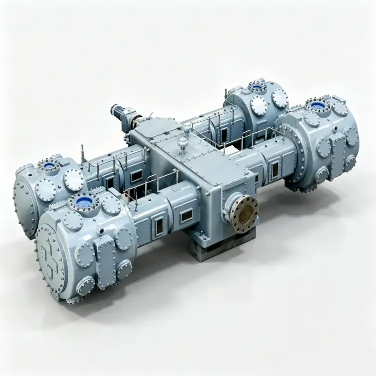
Fonctions de stockage à séparer
- tampon en amont
- Un réservoir basse pression placé entre la source d'azote et l'entrée du compresseur, qui amortit les fluctuations de pression et de débit de la source.
- récepteur en aval
- Un réservoir situé du côté refoulement du compresseur, qui stocke l'azote comprimé et régule la demande de l'utilisateur ou le cycle du compresseur.
- cycle du compresseur
- Des cycles répétés de démarrage-arrêt, de chargement-déchargement ou d'autres transitions de capacité se produisent lorsque les bandes de stockage et de contrôle sont trop petites pour la variabilité de la demande.
- stabilité de la pression
- La capacité de maintenir la pression d'aspiration ou de distribution dans la plage requise par le générateur, le compresseur et les utilisateurs du procédé.
- mélange de pureté
- La dilution ou la contamination qui se produit lorsque du gaz de pureté d'azote différente est admis dans un stockage commun.
- protection de secours
- Dispositifs de protection contre la pression et agencements de vannes qui maintiennent un récepteur et les sections bloquées qui y sont raccordées dans leur plage de pression nominale.
1. Placez le tampon en amont de manière à protéger la source d'azote.
Placez le réservoir tampon en amont après le générateur d'azote ou le système de contrôle du produit et avant l'aspiration du surpresseur. Ce réservoir doit recevoir un gaz produit ayant déjà atteint le niveau de pureté requis. Son signal de pression peut alors servir de signal de consigne pour l'aspiration du surpresseur et, le cas échéant, de signal de capacité pour le générateur. Le positionnement de ce réservoir à proximité du surpresseur permet également de réduire la longueur de la tuyauterie d'aspiration, dont la perte de charge doit être prise en compte pour le dimensionnement du compresseur.
Le réservoir tampon est particulièrement précieux lorsque la production est relativement stable, mais que le surpresseur prélève du gaz par à-coups. Dimensionnez sa capacité utile en fonction du déficit temporaire maximal entre la production et la demande du surpresseur. Si la demande dépasse la production pendant des heures plutôt que des secondes ou des minutes, un réservoir plus grand ne fera que repousser un problème de sous-dimensionnement de la production. Distinguez le stockage transitoire de la capacité permanente avant d'acheter le volume d'acier nécessaire.
2. Placer le stockage en aval là où il sert l'objectif de contrôle de la pression
Un réservoir aval est généralement installé après la compression, le refroidissement et toute séparation nécessaire afin que le réservoir reçoive le gaz à une température et des conditions acceptables. Il peut être situé près du compresseur pour stabiliser la régulation du déchargement, près d'un utilisateur à forte demande pour réduire les chutes de pression locales, ou au niveau d'un collecteur central. Son emplacement optimal dépend de la perte de charge, de l'espace disponible, des contraintes de sécurité et du mode de partage du réseau par plusieurs utilisateurs.
Avant de finaliser le choix de l'équipement, comparez cette tâche avec celle du site. réservoir récepteur d'azote Vérifiez la plage de pression et assurez-vous que la même pression de référence est utilisée. Ce contrôle croisé est lié au placement des réservoirs tampons remplis d'azote.
Si le compresseur est commandé par la pression du réservoir, utilisez le même point de pression pour les calculs de dimensionnement. Un manomètre placé au refoulement du compresseur peut indiquer une pression supérieure à celle d'un réservoir distant pendant le débit. Si les seuils de démarrage et d'arrêt sont définis par un transmetteur distant, tenez compte des pertes de charge et du temps de réponse du transmetteur. Lors de la mise en service, enregistrez simultanément la pression au refoulement du compresseur, dans le réservoir et sur la conduite principale de l'utilisateur pendant un épisode de consommation.
3. Dimensionner la capacité de stockage utile en tenant compte des déséquilibres de débit et des variations de pression.
La quantité de gaz utile stockée dans un réservoir dépend de la variation de pression absolue, du volume du réservoir, de la température du gaz et de la base de référence requise. Pour une première estimation en supposant un gaz parfait à température de réservoir approximativement constante, le volume standard utilisable est proportionnel au volume du réservoir multiplié par la différence entre les pressions absolues haute et basse, corrigée en fonction de la pression et de la température de référence choisies. Il convient d'utiliser les pressions absolues et une seule condition de référence.
Pour un réservoir tampon en amont, le déséquilibre de débit correspond au soutirage du surpresseur moins la production du générateur pendant la phase transitoire. Pour un récepteur en aval, il correspond à la demande des utilisateurs moins le débit du compresseur pendant la vidange du gaz stocké. Le temps nécessaire au réservoir pour compenser cette différence détermine le volume utile requis. Il convient d'ajouter une marge de sécurité pour la réponse du système de contrôle et l'incertitude, puis de vérifier le fonctionnement du réservoir et le comportement du compresseur plutôt que de compenser un sous-dimensionnement par un stockage excessif.


4. Utiliser l'emplacement du récepteur pour réduire les cycles de compression inutiles
Un petit réservoir haute pression à plage de régulation étroite permet à un compresseur à vitesse fixe de fonctionner fréquemment par cycles lorsque la demande moyenne est faible. Augmenter la capacité de stockage utile ou élargir la plage de pression admissible peut allonger le cycle, mais les pressions minimales et maximales définies par l'utilisateur constituent des limites. Un variateur de fréquence (VFD) peut s'avérer utile lorsque la demande varie de façon régulière, tout en conservant l'utilité du réservoir pour les variations brusques survenant plus rapidement que la capacité du compresseur à s'adapter.
Surveillez les démarrages, les déchargements et les variations de vitesse après la mise en service. Si le cycle est beaucoup plus rapide que prévu, vérifiez d'abord le profil de demande réel et l'emplacement du transmetteur de pression. Une fuite dans le réseau, un clapet anti-retour mal réglé ou des paramètres de contrôle trop restrictifs peuvent simuler un stockage insuffisant. Le récepteur fait partie d'un système de contrôle ; il est donc important de diagnostiquer les commandes et la demande avant d'ajouter un autre réservoir.
5. Préserver la pureté lorsque le stockage mélange l'azote au fil du temps
Un récepteur mélange du gaz neuf avec le stock existant. Cette méthode est utile pour lisser de légères fluctuations de pureté uniquement lorsque tout le gaz entrant est déjà conforme ; elle ne doit jamais servir à rendre un produit non conforme acceptable par dilution. Il est préférable de privilégier la vérification de la pureté et la purge de démarrage au stockage lorsque la contamination du réservoir serait difficile à corriger. Si des gaz de puretés différentes partagent un collecteur, il convient d'utiliser une séparation ou une analyse de mélange documentée plutôt que de supposer qu'un seul récepteur peut convenir à tous les utilisateurs.
Cette décision peut également être vérifiée auprès du site. compresseur d'azote alternatif Ces informations sont disponibles avant la publication de la fiche technique du projet. La vérification croisée porte ici sur l'emplacement des réservoirs tampons remplis d'azote.
Les composants internes du réservoir et la tuyauterie en aval doivent rester suffisamment propres pour le procédé. Les réservoirs neufs peuvent contenir des résidus de fabrication, de l'humidité ou des agents de conservation. Il convient de les nettoyer, de les sécher et de les purger conformément à une procédure approuvée avant de raccorder les utilisateurs critiques d'azote. Après maintenance, la pureté doit être rétablie par une purge contrôlée et une vérification à l'aide d'un analyseur, au lieu d'une remise en production immédiate du réservoir.
6. Instrumenter, isoler, drainer et soulager délibérément chaque vaisseau
Chaque réservoir tampon ou récepteur doit être équipé d'un indicateur de pression et des protections requises par son code de conception et des sources de surpression fiables. L'indication de température peut s'avérer utile pour le calcul des stocks ou les cycles thermiques. Il convient de prévoir une isolation permettant la maintenance sans pour autant laisser le réservoir connecté à une source de pression active sans soupape de décharge. Les clapets anti-retour ne doivent pas créer de zones piégées cachées entre un compresseur et une vanne d'isolement fermée.
Installez des purgeurs aux points bas du réservoir lorsque des infiltrations de liquide ou de la condensation sont probables, et assurez-vous de leur bon fonctionnement. Les voies d'évacuation et de dépressurisation doivent tenir compte de l'accumulation d'azote. Pour les systèmes critiques, évaluez si l'isolation d'un réservoir entraîne la suppression de toute capacité de stockage et la déstabilisation des commandes du compresseur restantes ; un système de dérivation ou un mode de fonctionnement alternatif peut s'avérer nécessaire pendant l'inspection.
Tableau de placement des tampons et des récepteurs
| Article | Question d'ingénierie | Signal de vérification ou de décision |
|---|---|---|
| tampon en amont | Quel palier transitoire entre production et suralimentation doit-il franchir ? | La pression d'aspiration reste supérieure au minimum du surpresseur sans perturber le fonctionnement du générateur. |
| Récepteur en aval | Quel pic d'utilisation ou intervalle de cyclage le stockage doit-il couvrir ? | La pression dans le collecteur reste dans la plage de fonctionnement tandis que la régulation du compresseur reste stable. |
| Limite de pureté | Des gaz non conformes peuvent-ils se retrouver dans les stocks entreposés ? | Le système d'analyse et de ventilation protège le récepteur avant l'admission de gaz non conforme. |
| Protection contre la pression | Un système de vannes peut-il isoler un vaisseau du système de décharge ? | Chaque récepteur et section piégée conserve une protection contre la surpression valide. |
| Consignez la décision finale dans la demande de devis, le dossier de mise en service ou le dossier de maintenance afin qu'un autre ingénieur puisse la reproduire. | ||
Feuille de vérification du projet
Vérifiez la stabilisation du débit du générateur en créant une condition contrôlée permettant d'interpréter conjointement le fonctionnement du tampon amont et le cycle du compresseur. Stabilisez le système, notez la pression, la température, le débit ou l'état de la machine, le cas échéant, et utilisez des instruments étalonnés ou une inspection directe aux emplacements désignés. Déterminez quel réservoir stabilise le débit du générateur et lequel répond à la demande en gaz comprimé, et consignez les réponses attendues et observées. Si une limite spécifique au modèle est requise, consultez la documentation du compresseur, du réservoir, de la tuyauterie, du générateur ou du procédé concerné, plutôt que d'utiliser une valeur générique. Le compte rendu doit justifier techniquement la décision finale.
Avant de clôturer l'ordre de travail, assurez-vous que la définition des plages de pression haute et basse à l'aide de la pression absolue pour les calculs de stockage soit traçable. Pour le récepteur aval, consignez le point de référence et l'unité ou son état physique ; pour la stabilité de la pression, consignez le point de comparaison qui confirme le bon fonctionnement du système. Reliez ces observations à l'atténuation des variations d'aspiration et à la charge ou au mode de fonctionnement réel. Une valeur sans localisation ni état est difficilement réutilisable. Si le contrôle révèle une anomalie, corrigez la restriction, l'état de la commande, l'état du composant ou l'hypothèse de conception qui en est la cause, puis répétez l'observation afin de prouver la réparation et non de la supposer.
Considérez la « couverture de la demande de pointe » comme une petite expérience de mise en service. Définissez l'état initial, observez le cycle du compresseur, modifiez uniquement la variable nécessaire au test approuvé et surveillez la réponse du mélange de pureté. L'action « Calculer le déséquilibre maximal à court terme entre la production et la demande, ainsi que sa durée » doit consigner l'état initial, l'intervention, l'état final et toute alarme ou réponse de contrôle. Ceci est utile lorsque plusieurs composants peuvent produire le même symptôme. En modifiant un seul facteur à la fois et en maintenant le compresseur dans sa plage de fonctionnement approuvée, l'équipe peut distinguer la cause du hasard et éviter de remplacer du matériel non responsable.
Lorsque l'enveloppe du processus est stable, le site compresseur d'azote de grande capacité Cette page fournit une liste pratique du matériel nécessaire pour l'étape de sélection suivante. La vérification croisée porte ici sur l'emplacement des réservoirs tampons remplis d'azote.
Pour une fiabilité à long terme, il est essentiel de connecter les instruments de pression et de pureté à un système dont les relevés contrôlent le niveau de stock prévu, en établissant une ligne de base de stabilité de pression. Enregistrez cette ligne de base lorsque l'installation est propre, stable et en bon état de fonctionnement, puis intégrez les dispositifs de décharge et la charge de fonctionnement afin de normaliser les relevés ultérieurs. Le principe de « réduction des cycles du compresseur » doit comporter un seuil d'alerte défini, même si la valeur absolue n'a pas atteint le niveau d'alarme. Un écart progressif par rapport à une ligne de base reproductible est souvent plus préoccupant qu'un relevé isolé. En cas de modification de la configuration du procédé, établissez une nouvelle ligne de base documentée plutôt que de comparer des états de fonctionnement différents.
Limite de sécurité et de vérification
Le dimensionnement et l'emplacement du récepteur font partie des activités de conception des systèmes sous pression. Il convient d'utiliser les codes relatifs aux cuves, la pression de conception certifiée, les calculs de décharge, les exigences sismiques ou éoliennes du site, le cas échéant, et la conception des supports structurels. Les rejets d'azote peuvent créer des atmosphères appauvries en oxygène, en particulier autour des cuves et des fosses intérieures. Il est impératif d'isoler, de dépressuriser et de verrouiller les sources de pression, et de vérifier l'absence d'énergie avant d'ouvrir les raccords de la cuve ou les instruments.
Liste de contrôle de conception du récepteur
- Identifiez quel réservoir stabilise la production du générateur et lequel répond à la demande en gaz comprimé.
- Définir les plages de pression haute et basse en utilisant la pression absolue pour les calculs de stockage.
- Calculez le plus grand déséquilibre à court terme entre l'offre et la demande et sa durée.
- Placez les instruments de pression et de pureté là où leurs relevés contrôlent le stock prévu.
- Vérifier l'isolation du récepteur, les clapets anti-retour, les purges, la dépressurisation et les limites de décharge.
- Cycles de tendance et pression lors de la mise en service pour vérifier que le stockage remplit sa fonction.
Questions sur les récepteurs d'azote
Un seul récepteur peut-il alimenter les deux côtés du compresseur ?
Non. Le compresseur crée deux systèmes de pression distincts. Un tampon en amont et un réservoir en aval remplissent des fonctions différentes et sont dimensionnés et contrôlés pour des plages de pression différentes.
Un récepteur plus grand permet-il toujours de réduire la consommation d'énergie ?
Cela permet de réduire les cycles de fonctionnement et d'assurer une régulation plus stable, mais un stockage surdimensionné engendre des coûts supplémentaires et peut accroître les fuites ou les pertes de charge. Les performances énergétiques dépendent de la stratégie de régulation du compresseur et de la plage de pression requise.
L'analyseur d'oxygène doit-il être placé avant ou après le récepteur ?
Pour protéger le produit stocké, vérifiez sa pureté avant l'admission du gaz dans le récepteur. Un contrôle qualité supplémentaire en aval peut également être requis par le plan qualité du procédé.
Principe de placement du stockage
Installez le tampon amont pour stabiliser la source d'azote et l'aspiration du compresseur ; installez le réservoir aval pour répondre aux besoins en haute pression et assurer la régulation. Dimensionnez chaque élément en fonction de son propre déséquilibre de débit, de sa durée de fonctionnement et de la variation de pression admissible, puis vérifiez la pureté, la décharge, le drainage et le comportement de la régulation à l'emplacement réel des instruments.

























