
Wybór lokalizacji sprężarki azotu w lokalnym systemie N2
Sprężarka powinna znajdować się w miejscu, w którym może otrzymywać stabilny, czysty azot i dostarczać ciśnienie bez zakłócania pracy generatora, odprowadzania wody, chłodzenia lub dostępu serwisowego.
Nie ma jednej fizycznej lokalizacji, która pasowałaby do każdego lokalnego systemu azotowego, ale sekwencja procesu jest zazwyczaj jasna: wytwarzanie azotu, jego stabilizacja, podnoszenie ciśnienia tylko wtedy, gdy wymagane jest wyższe ciśnienie, chłodzenie i oddzielanie kondensatu, jeśli to konieczne, magazynowanie produktu pod wysokim ciśnieniem, a następnie zasilanie kolektora dystrybucyjnego. Kluczową decyzją jest to, czy sprężarka jest maszyną sprężającą powietrze przed generacją azotu, czy też urządzeniem wspomagającym azot za generatorem. Nie należy mylić tych funkcji. Sprężarka azotu, której zadaniem jest zachowanie czystości produktu, zazwyczaj znajduje się za urządzeniami wytwarzającymi czystość, z odbiornikiem produktu przed wlotem i odbiornikiem końcowym po sprężaniu, gdy wymagane jest magazynowanie. Na podstawie tej lokalizacji procesu należy wybrać rzeczywiste położenie pomieszczenia lub palety pod kątem spadku ciśnienia ssania, instalacji chłodniczych, przebiegu odpowietrzników, fundamentu, klasyfikacji stref niebezpiecznych i odstępu konserwacyjnego.
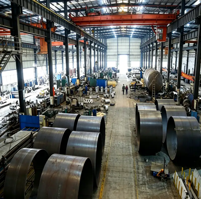
Lokalizacje systemu do identyfikacji
- wyjście generatora
- Połączenie produktu z azotem opuszczające PSA, membranę lub inny generator. Jego ciśnienie, czystość i przepływ definiują punkt wyjścia dla dalszego wzmocnienia.
- odbiorca produktu
- Zbiornik niskociśnieniowy za generatorem, który stabilizuje ssanie wspomagające i oddziela produkcję gazu od krótkotrwałych wahań zapotrzebowania.
- wlot wzmacniacza
- Przyłącze ssące sprężarki, w tym rzeczywiste ciśnienie i temperatura po stratach w rurociągach od odbiornika produktu.
- chłodnica końcowa
- Wymiennik ciepła służący do obniżania temperatury gazu po sprężeniu przed jego przekazaniem do dalszych rurociągów, rozdzieleniem, magazynowaniem lub użyciem.
- odbiorca końcowy
- Magazynowanie sprężonego azotu, które wyrównuje zapotrzebowanie, zmniejsza liczbę cykli i zapewnia stabilne dostawy do sieci dystrybucyjnej.
- nagłówek dystrybucyjny
- Sieć rurociągów zakładu dostarczająca azot użytkownikom w określonym zakresie ciśnień i o określonych warunkach jakościowych.
1. Określ położenie procesu przed ustaleniem położenia podłogi
Narysuj proces jako bloki funkcjonalne. Jeśli w zakładzie zastosowano sprężarkę powietrza zasilającego do agregatu PSA lub membranowego, maszyna ta nie wykonuje tej samej pracy, co dozownik azotu umieszczony za nią. Sprężarka powietrza zasilającego tłoczy powietrze atmosferyczne i musi spełniać wymagania dotyczące jakości powietrza generatora. Sprężarka N2 umieszczona za nią tłoczy już odseparowany azot i jest dobierana pod kątem czystości produktu, ciśnienia ssania i wymaganego ciśnienia końcowego. Należy wyraźnie oznaczyć obie maszyny na liście wyposażenia i dokumentacji technicznej.
W przypadku wzmacniacza umieszczonego w dół strumienia, należy umieścić odbiornik produktu lub inną objętość stabilizującą przed wlotem, gdy generator nie jest w stanie bezpośrednio obsłużyć szybkiego poboru. Należy umieścić weryfikację czystości przed zbiornikiem wysokociśnieniowym, aby gaz niezgodny ze specyfikacją nie był wzmacniany, powodując problem z dużym zapasem. Ten układ funkcjonalny określa położenie zaworów zwrotnych, izolacji, odpowietrzników, analizatorów i zezwoleń sterujących przed rozpoczęciem montażu mechanicznego.
2. Utrzymuj rurę ssącą wzmacniacza krótką, wystarczająco dużą i przewidywalną
Po ustaleniu położenia procesu należy zminimalizować straty ciśnienia ssania, których można uniknąć. Sprężarki tłokowe są wrażliwe na ograniczenia wlotowe, ponieważ niższe ciśnienie ssania w cylindrze zmniejsza przepływ masowy i zwiększa stopień sprężania. Długa, zbyt mała średnica rury z wieloma kolankami może spowodować, że ciśnienie na wlocie do sprężarki będzie znacznie niższe niż sugeruje manometr. Dobór rozmiaru przewodu ssącego powinien być dokonywany na podstawie dopuszczalnego spadku ciśnienia i pulsacji, a nie wyłącznie na podstawie średnicy przyłącza.
Następnym przydatnym sprawdzeniem jest witryna przemysłowy kompresor N2 Materiał, zwłaszcza gdy ciśnienie, czystość i wymagania dotyczące ciągłej pracy są ze sobą powiązane. Weryfikacja krzyżowa jest tutaj powiązana z miejscem instalacji sprężarki azotu.
Unikaj umieszczania sprężarki tak daleko od odbiornika produktu, że linia stanie się ukrytym źródłem spadku wydajności. Jeśli separacja jest nieunikniona, oblicz spadek ciśnienia przy maksymalnym przepływie i sprawdź działanie sprężarki w porównaniu z minimalnym oczekiwanym ciśnieniem wlotowym. Zapewnij niezależne podparcie linii, aby obciążenia dysz i wibracje nie przenosiły się na obudowę sprężarki ani przyłącza cylindra.
3. Zaplanuj schładzanie, odwodnienie i ostateczne przechowywanie jako część lokalizacji
Strona tłoczna wymaga miejsca na chłodnicę końcową, separator lub układ spustowy, tam gdzie ma to zastosowanie, zawór zwrotny, zabezpieczenie nadmiarowe, oprzyrządowanie i często końcowy odbiornik. Gorące przewody tłoczne nie powinny być prowadzone przez zatłoczone obszary robocze tylko dlatego, że sprężarka mieści się w dogodnym narożniku. Należy zapewnić układ umożliwiający odprowadzanie ciepła i przepływ kondensatu do wyznaczonych punktów spustowych, zamiast gromadzenia się w niskich kieszeniach.
Odbiornik końcowy jest najbardziej użyteczny, gdy znajduje się hydraulicznie blisko buforowanego zapotrzebowania, ale ze względów bezpieczeństwa lub ze względu na przestrzeń może on zostać umieszczony oddzielnie od sprężarki. Należy uwzględnić spadek ciśnienia na wylocie sprężarki do odbiornika oraz między odbiornikiem a kolektorem rozdzielczym. Jeśli użytkownicy mają bardzo zróżnicowane poziomy ciśnienia, należy rozważyć, czy lokalne regulacje lub dedykowane podnoszenie ciśnienia nie są bardziej efektywne niż utrzymywanie całego kolektora na najwyższym ciśnieniu.

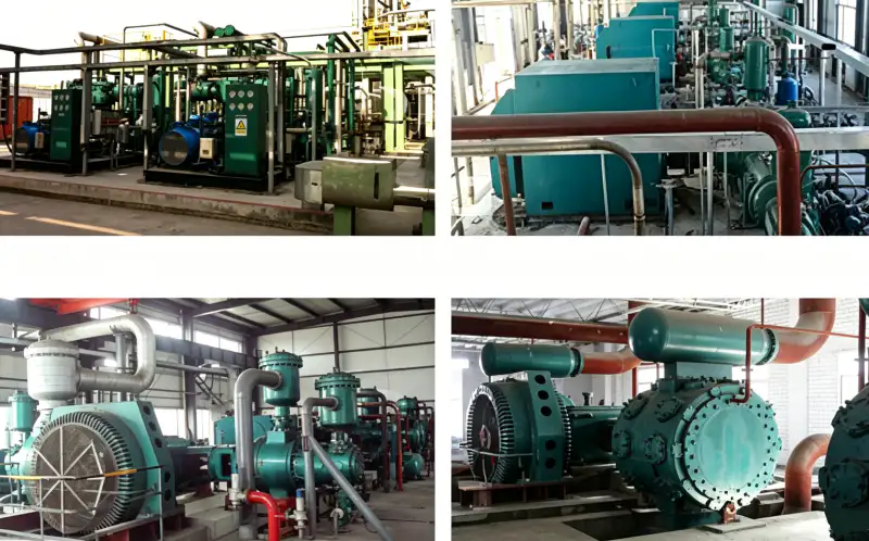
4. Dopasuj pomieszczenie techniczne do potrzeb chłodzenia i środowiska
Sprężarka chłodzona powietrzem lub chłodnica końcowa wymagają czystego przepływu powietrza i możliwości odprowadzenia gorącego powietrza wylotowego z pomieszczenia. Recyrkulacja gorącego powietrza może jednocześnie podnieść temperaturę ssania i chłodzenia, zmniejszając margines bezpieczeństwa w upalne dni. System chłodzony wodą wymaga niezawodnego przepływu wody chłodzącej, odpowiedniej jakości, izolacji, odwodnienia i dostępu do czyszczenia wymiennika. W obu przypadkach do analizy termicznej należy użyć najgorszych przewidywanych warunków otoczenia lub wody chłodzącej.
Sprawdź klasyfikację obszaru, wentylację, hałas, narażenie na warunki atmosferyczne, zapylenie, atmosferę korozyjną i ryzyko powodzi. Sam azot nie jest łatwopalny, ale sprężarka może znajdować się w obszarze procesowym, którego klasyfikacja elektryczna zależy od innych materiałów. Dobór sprzętu, silników, instrumentów i wentylacji powinien zatem być zgodny z zasadami dotyczącymi stref niebezpiecznych, a nie z ogólnym założeniem, że praca z azotem zawsze jest niesklasyfikowana.
5. Zapewnij dostęp konserwacyjny o takiej samej wadze, jak długość rury
Lokalizacja, która pozwala zaoszczędzić dwa metry rurociągu, ale uniemożliwia demontaż zaworu, tłoka, uszczelnienia, chłodnicy lub silnika, jest nieodpowiednia. Należy przestrzegać zaleceń producenta dotyczących zakresu konserwacji i podnoszenia. Należy upewnić się, że istnieje możliwość demontażu największego elementu serwisowego bez konieczności demontażu niezwiązanego z nim rurociągu. Zapewnić dostęp do zaworów spustowych, punktów poboru próbek, filtrów, zaworów odcinających, manometrów i zaworów bezpieczeństwa z bezpiecznej pozycji roboczej.
Aby zachować te same zasady dla zespołów inżynieryjnych i zakupowych, należy odnieść to wymaganie do lokalizacji sprężarka azotu bezolejowa Informacje. Weryfikacja krzyżowa jest tutaj powiązana z tym, gdzie powinien być zainstalowany kompresor azotu.
Trzymaj panele przyrządów i obudowy elektryczne z dala od gorących powierzchni wyładowczych i niekontrolowanych otworów wentylacyjnych. Zapewnij oświetlenie i stabilną platformę roboczą w miejscu przeprowadzania rutynowych przeglądów. Jeśli dwie sprężarki zapewniają redundancję, nie umieszczaj ich tak ciasno, aby konserwacja jednej blokowała wentylację lub wymagała wyłączenia drugiej. Łatwość konserwacji jest elementem dostępności, a nie udogodnieniem po zakończeniu budowy.
6. Sprawdź wybraną lokalizację, przechodząc przez stany operacyjne
Przed zamrożeniem układu, przejrzyj schemat orurowania i sterowania, przechodząc przez etapy rozruchu, normalnej pracy, wysokiego zapotrzebowania, wyłączenia sprężarki, wyłączenia generatora, odcięcia konserwacyjnego i dekompresji. Zapytaj, którędy przepływa gaz w każdym przypadku i czy operator widzi i dociera do wymaganego zaworu. Upewnij się, że zablokowana sekcja jest zabezpieczona przez zawór nadmiarowy i że zawór zwrotny nie może utworzyć nieuwolnionej objętości.
Podczas rozruchu należy zmierzyć rzeczywiste ciśnienie na wylocie generatora, odbiorniku produktu, wlocie wzmacniacza, wylocie wzmacniacza, odbiorniku końcowym i kolektorze dystrybucyjnym przy znanym przepływie. Te jednoczesne odczyty ujawnią, czy fizyczna lokalizacja i przebieg rurociągów spowodowały większe ograniczenie niż założono w projekcie. Należy je zachować jako punkt odniesienia do późniejszych zmian, gdy do sieci azotowej zostaną podłączeni kolejni użytkownicy.
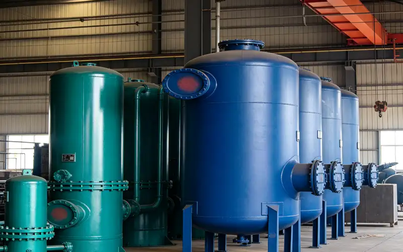
Tabela przeglądu lokalizacji
| Przedmiot | Pytanie inżynierskie | Sygnał weryfikacji lub decyzji |
|---|---|---|
| Sekwencja procesu | Czy ta sprężarka obsługuje powietrze czy produktowy azot? | PFD wyraźnie oddziela sprężanie powietrza zasilającego od doładowania N2. |
| Ścieżka ssąca | Jakie ciśnienie dociera do wlotu wzmacniacza przy maksymalnym przepływie? | Zmierzona lub obliczona strata utrzymuje ssanie w zakresie doboru sprężarki. |
| Media i ciepło | Czy pomieszczenie może odrzucić sprężarkę i chłodniejsze ciepło w najgorszych warunkach? | Projekt wentylacji lub chłodzenia wodnego jest weryfikowany pod kątem środowiska panującego na miejscu. |
| Dostęp do usługi | Czy można bezpiecznie usunąć główne podzespoły? | Przestrzenie konserwacyjne i drogi podnoszenia określone przez producenta pozostają niezakłócone. |
| Zapisz ostateczną podstawę w zapytaniu ofertowym, pliku uruchomienia lub rejestrze konserwacji, aby inny inżynier mógł powtórzyć decyzję. | ||
Arkusz weryfikacji projektu
Podczas przeglądu technicznego należy zakwestionować założenie „wybierz pozycję górną lub dolną”, śledząc fizyczną ścieżkę powiązaną z wylotem generatora i wlotem wzmacniacza. Prześledź drogę gazu, ciepła, siły, sygnału sterującego lub wycieku od źródła do miejsca przeznaczenia i zidentyfikuj każdy komponent, który może wpłynąć na wynik. Następnie wykonaj „Narysuj generator, odbiornik niskiego ciśnienia, wzmacniacz, chłodnicę końcową, odbiornik końcowy i kolektor jako oddzielne bloki” w punkcie, w którym decyzja jest faktycznie podejmowana, a nie przy najdogodniejszym manometrze. Zapisz każdy spadek ciśnienia, różnicę temperatur, opóźnienie sterowania lub ustalenia z inspekcji wyjaśniające zachowanie. Ta kontrola oparta na ścieżce zapobiega interpretacji lokalnych pomiarów bez kontekstu systemu.
Uczyń weryfikację „Oblicz spadek ciśnienia ssania wzmacniacza przy maksymalnym przepływie i minimalnym ciśnieniu w odbiorniku” użyteczną podczas przyszłego badania usterki. Zapisz stan odbiornika produktu, chłodnicy końcowej, sprężarki, stan zapotrzebowania i czas obserwacji w jednym rekordzie. Powiąż ten rekord z założeniem projektowym „oddzielne funkcje generowania i wzmacniania” i zanotuj, który rysunek, instrukcja, specyfikacja procesu lub skalibrowane narzędzie ustanowiły akceptację. Jeśli odczyt jest prawidłowy, staje się on punktem odniesienia. Jeśli jest nieprawidłowy, udokumentuj działania naprawcze i powtórz test w tych samych warunkach. Spójne zapisy zmniejszają pokusę kompensowania niewyjaśnionego problemu poprzez zwiększenie ciśnienia, prędkości, limitów temperatury lub niepowiązanych ustawień.
Zweryfikuj „zabezpieczenie stabilności ssania” na granicy, gdzie występują jego konsekwencje. Obserwuj wlot sprężarki u źródła i odbiornik końcowy po stronie odbiorczej, a następnie wykonaj „Potwierdź, że odprowadzanie ciepła z chłodnicy końcowej, spusty, urządzenia nadmiarowe i układ odpowietrzania są odpowiednie”, dopóki odpowiedni przepływ i ciśnienie są stabilne. Zapisz wystarczająco dużo kontekstu, aby odróżnić normalne odchylenia procesu od pogorszenia stanu sprzętu. Jeśli dokładne limity akceptacji zależą od wybranego modelu, skorzystaj z aktualnej dokumentacji producenta lub zatwierdzonej specyfikacji projektu. Nie przenoś wartości z innej sprężarki tylko dlatego, że usługa wydaje się podobna. Zapis od granicy do granicy znacznie przyspiesza późniejsze rozwiązywanie problemów.
Aby przeprowadzić kontrolę krzyżową dotyczącą konkretnej aplikacji, skorzystaj z witryny sprężarka N2 o wysokim przepływie strona obok danych pomiarowych omówionych powyżej. Weryfikacja krzyżowa jest tutaj powiązana z miejscem montażu sprężarki azotu.
Zamknij pętlę „Sprawdź klasyfikację stref niebezpiecznych, ekstremalne warunki otoczenia, hałas, zapylenie i narażenie na warunki atmosferyczne”, dokumentując przyczynę, reakcję i akceptację. Zacznij od „zaplanowania chłodzenia i drenażu”, zidentyfikuj oczekiwane zachowanie chłodnicy końcowej i wybierz drugą obserwację dotyczącą kolektora dystrybucyjnego, która może niezależnie potwierdzić ten sam wniosek. Przeprowadź kontrolę bez pomijania zabezpieczeń ani przekraczania zatwierdzonego zakresu roboczego. Jeśli oba sygnały się nie zgadzają, sprawdź dokładność przyrządu, stan zaworów, spadek ciśnienia, zanieczyszczenie, nieszczelność lub logikę sterowania, zanim zdecydujesz, który element wymaga naprawy. Niezależne potwierdzenie jest cenne, gdy wyłączenie lub wymiana byłyby kosztowne.
Granica bezpieczeństwa i weryfikacji
Sprężony azot może stwarzać zagrożenia zarówno w postaci magazynowania energii, jak i niedoboru tlenu. Należy zlokalizować otwory wentylacyjne i zrzuty nadmiarowe, aby uwolniony gaz nie mógł gromadzić się w pomieszczeniach zajmowanych przez ludzi, wykopach lub zamkniętych pomieszczeniach. Zapewnić wentylację na podstawie oceny zagrożenia na miejscu. Przed konserwacją należy odizolować i rozhermetyzować odbiorniki oraz każdą uwięzioną objętość rurociągu; nie należy polegać na pojedynczym manometrze ani zaworze zwrotnym jako dowodzie braku energii.
Lista kontrolna zatwierdzania układu
- Narysuj generator, zbiornik niskiego ciśnienia, wzmacniacz, chłodnicę końcową, zbiornik końcowy i kolektor jako oddzielne bloki.
- Oblicz spadek ciśnienia ssania wzmacniacza przy maksymalnym przepływie i minimalnym ciśnieniu w odbiorniku.
- Sprawdź, czy odprowadzanie ciepła z chłodnicy końcowej, odpływy, urządzenia nadmiarowe i przewody odpowietrzające są odpowiednie do danego miejsca.
- Sprawdź klasyfikację obszarów niebezpiecznych, ekstremalne warunki otoczenia, hałas, zapylenie i narażenie na warunki atmosferyczne.
- Sprawdź odstępy serwisowe i ścieżki podnoszenia/demontażu na podstawie wybranego rysunku sprężarki.
- Podczas uruchamiania należy zmierzyć ciśnienie w każdym głównym węźle i zachować wartość bazową.
Pytania dotyczące lokalizacji sprężarki
Czy odbiornik końcowy powinien znajdować się obok kompresora?
Niekoniecznie. Powinien być zlokalizowany w miejscu, w którym magazyn służy celowi kontroli ciśnienia, jednocześnie spełniając wymagania bezpieczeństwa, konstrukcyjne i rurociągowe. Należy uwzględnić spadek ciśnienia w rurociągu w obu konfiguracjach.
Czy wzmacniacz azotu można zamontować bezpośrednio za generatorem bez odbiornika?
Tylko wtedy, gdy generator i sprężarka zostały sprawdzone jako układ sprzężony i tolerują te same stany przejściowe, do stabilizacji interfejsu powszechnie stosuje się odbiornik produktu.
Czy lokalizacja na zewnątrz zawsze jest lepsza dla wentylacji azotem?
Montaż na zewnątrz może zmniejszyć ryzyko akumulacji, ale wiąże się z ryzykiem wystąpienia czynników atmosferycznych, temperatury, korozji, hałasu i problemów z konserwacją. Zamiast stosować jedną zasadę, należy kierować się kryteriami dotyczącymi zagrożeń i środowiska w projekcie.
Zasada umieszczania
Najpierw zainstaluj sprężarkę azotu we właściwym punkcie procesu, a następnie zoptymalizuj jej położenie pod kątem strat ssania, chłodzenia, odpływu, bezpieczeństwa i dostępu do konserwacji. Dobre rozmieszczenie ułatwia pomiar i izolację wylotu generatora, zbiornika, wlotu wzmacniacza, chłodnicy końcowej, zbiornika końcowego i kolektora rozdzielczego jako odrębnych węzłów systemu.

























