
Wykorzystanie sprężarek azotowych do osłonowania i inertyzacji zbiorników
Osłona kontroluje niewielkie ciśnienie ochronne podczas pracy; inertyzacja zmienia atmosferę zbiornika. Rozmiar sprężarki musi uwzględniać oba te czynniki, nie zakłócając działania systemu odpowietrzania zbiornika.
Osłanianie zbiornika i zobojętnianie go azotem to powiązane, ale różne zadania związane z azotem. Osłanianie zastępuje gaz podczas pobierania cieczy lub zmian temperatury, utrzymując niewielkie nadciśnienie, które ogranicza wnikanie powietrza. Zobojętnianie lub przedmuchiwanie celowo zmienia atmosferę, często przed uruchomieniem, konserwacją lub wprowadzeniem materiału wrażliwego lub niebezpiecznego. Sprężarka lub źródło azotu muszą zostać dobrane z uwzględnieniem sterowania zapotrzebowaniem, ale źródło wysokiego ciśnienia jest zazwyczaj regulowane przed zbiornikiem. Nigdy nie należy używać ciśnienia tłoczenia sprężarki jako metody kontroli ciśnienia w zbiorniku. Dopuszczalne ciśnienie i podciśnienie w zbiorniku zależą od jego konstrukcji i systemu odpowietrzania, podczas gdy ciśnienie zasilania azotem wymaga jedynie wystarczającego marginesu, aby regulatory, zawory i orurowanie mogły zapewnić wymagany przepływ.

Terminy dotyczące inertyzacji zbiornika
- okrywanie zbiornika
- Kontrolowane dodawanie azotu w celu utrzymania ochronnego ciśnienia w przestrzeni parowej w przypadku zmian poziomu zbiornika, temperatury lub objętości pary.
- inertyzacja
- Zastosowanie azotu w celu obniżenia stężenia tlenu lub gazów reaktywnych do określonego bezpiecznego lub procesowego stanu.
- wnikanie tlenu
- Przedostawanie się powietrza przez otwory wentylacyjne, uszczelnienia, włazy, otwory podciśnieniowe lub przyłącza procesowe, które mogą uniemożliwić wytworzenie zamierzonej atmosfery obojętnej.
- ciśnienie koca
- Niskie ciśnienie pary w przestrzeni międzykontynentalnej utrzymywane przez układ sterowania osłoną, ograniczone przez konstrukcję zbiornika i ustawienia odpowietrznika.
- zawór sterujący
- Regulator lub zawór, który dozuje azot z układu zasilającego do zbiornika na podstawie ciśnienia lub zapotrzebowania procesu.
- system wentylacyjny
- Normalny i awaryjny sprzęt odpowietrzający, który chroni zbiornik przed ciśnieniem i podciśnieniem, jednocześnie odpowiednio kierując wypierane opary.
1. Określ, czy obowiązkiem jest osłona, inertyzacja czy obie te czynności
W przypadku osłony, oblicz zapotrzebowanie na azot na podstawie maksymalnego wypompowania cieczy, skurczu termicznego, kondensacji pary wodnej, tam gdzie ma to zastosowanie, oraz założeń dotyczących nieszczelności ustalonych metodą projektowania zbiornika. Zapotrzebowanie może być okresowe i znacznie mniejsze niż w przypadku przedmuchu. W przypadku inertyzacji, zdefiniuj objętość zbiornika, początkowe i docelowe parametry tlenu, metodę przedmuchu, sposób mieszania oraz wymagany czas zakończenia. Potraktuj te elementy jako osobne wiersze na liście obciążenia azotem.
Przypadek sprężarki sterującej może być zaplanowanym zdarzeniem inertyzacji, a nie ciągłym zatrzymywaniem. Jeśli inertyzacja może wystąpić, gdy aktywni są inni użytkownicy, należy uwzględnić tę współbieżność. Alternatywnie, można wykorzystać zbiornik retencyjny lub tymczasowe źródło zasilania do rzadkich przedmuchów o dużej objętości, aby stała sprężarka nie była przewymiarowana do normalnej pracy zbiornika.
2. Utrzymuj azot pod wysokim ciśnieniem przed regulacją
Sprężarka lub wzmacniacz może napełniać zbiornik pod ciśnieniem odpowiednim do dystrybucji w zakładzie, ale zbiornik powinien być zasilany azotem poprzez regulację ciśnienia zaprojektowaną do pracy w systemie podciśnieniowym. Regulator lub zawór sterujący musi mieć wystarczającą wydajność przy minimalnym ciśnieniu zasilania, aby zapewnić maksymalny dopływ, utrzymując jednocześnie wymagane niskie ciśnienie w zbiorniku. W przypadku dużych wahań ciśnienia zasilania odpowiednie może być zastosowanie regulacji dwustopniowej lub dedykowanego sterowania lokalnego.
Nie należy zwiększać ciśnienia podciśnieniowego w zbiorniku, aby skompensować zbyt mały przekrój przewodu azotowego. Należy zmierzyć ciśnienie zasilania przed i za regulatorem podczas maksymalnego zapotrzebowania. Jeśli ciśnienie przed zaworem spadnie, należy sprawdzić wydajność sprężarki, zbiornika lub kolektora. Jeśli ciśnienie występuje przed zaworem, ale nie przy zbiorniku, należy sprawdzić rozmiar regulatora, filtry, ograniczenia przewodu lub konfigurację zaworów.
Następnym przydatnym sprawdzeniem jest witryna sprężarka azotu do osłony zbiornika Materiał, zwłaszcza gdy ciśnienie, czystość i wymagania dotyczące ciągłej pracy są ze sobą powiązane. Weryfikacja krzyżowa jest tutaj powiązana z zastosowaniem sprężarek N₂, zbiorników z chemikaliami i osłoną zobojętniającą.
3. Koordynacja dodawania azotu z systemem odpowietrzania i próżni
Azot wnikający do zbiornika wypiera parę, która musi wydostać się przez zaprojektowaną ścieżkę odpowietrzającą. Podczas szybkiego płukania z inertyzacją, przepływ przez odpowietrznik może być znacznie większy niż podczas normalnego płukania. Należy upewnić się, że układ odpowietrzający jest w stanie przepuścić planowany przepływ przez odpowietrznik, nie przekraczając ciśnienia w zbiorniku. Jednocześnie, normalne wypompowywanie nie może wytwarzać podciśnienia szybciej niż azot lub zawór upustowy może zareagować.
Sprawdź interakcje między zaworem osłonowym, odpowietrznikiem ciśnieniowo-próżniowym, systemem odzyskiwania oparów, pochodnią lub kolektorem odpowietrzającym oraz wszelkimi awaryjnymi urządzeniami bezpieczeństwa. Większa wydajność zasilania azotem może stworzyć nowy scenariusz nadciśnienia w przypadku awarii zaworu sterującego. Badanie ochrony zbiornika powinno uwzględniać maksymalny wiarygodny dopływ azotu z regulowanego systemu.
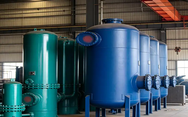
4. Zapobiegaj przedostawaniu się tlenu, utrzymując zamierzony zakres ciśnienia
Osłanianie działa tylko wtedy, gdy ciśnienie w zbiorniku pozostaje nieznacznie dodatnie w stosunku do otaczającej atmosfery w dopuszczalnym zakresie. Nieszczelne włazy, otwarte porty pobierania próbek, uszkodzone uszczelki lub zjawiska próżni mogą powodować przedostawanie się powietrza nawet przy dostępności azotu. Należy śledzić ciśnienie w zbiorniku i przepływ azotu. Rosnący przepływ bazowy może wykryć wyciek lub problem z zaworem, zanim stężenie tlenu znacząco wzrośnie.
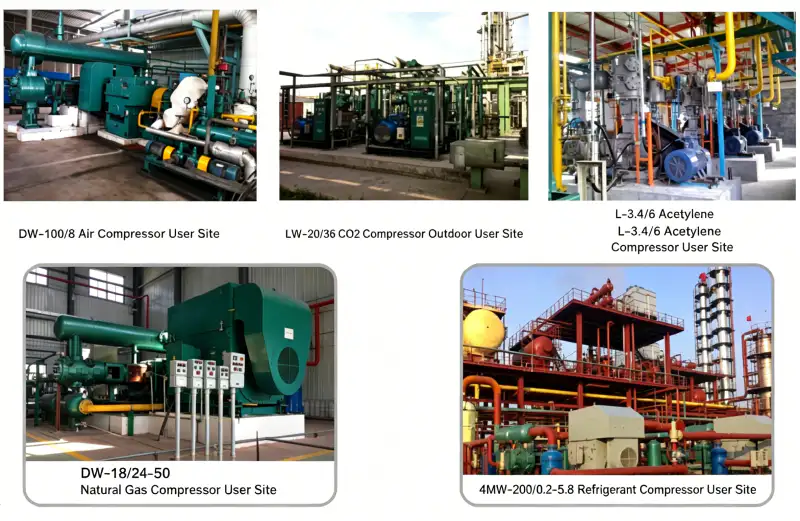
W przypadku gdy proces wymaga zweryfikowanych warunków obojętnych, należy zastosować metodę pomiaru tlenu i miejsce poboru próbek, które odzwierciedlają atmosferę zbiornika. Gaz w pobliżu wlotu azotu może wydawać się akceptowalny, zanim odległe części zbiornika zostaną całkowicie przemieszczone. Punkt końcowy przedmuchu powinien być określony przez procedurę bezpieczeństwa procesu, a nie przez ustaloną liczbę minut pracy sprężarki.
5. Dobierz rozmiar sprężarki i odbiornika z listy ładunków azotu
Należy dodać stałe obciążenia osłonowe, które mogą występować jednocześnie, i zidentyfikować oddzielne przejściowe obciążenia zobojętniające. Sprężarka powinna utrzymywać zapasy w odbiorniku przez cały okres stałego zapotrzebowania. Objętość odbiornika może pokryć krótkotrwałe okresy wysokiego przepływu między wysokim a niskim ciśnieniem, pozostawiając nadal odpowiednie ciśnienie wlotowe regulatora. Do obliczenia pojemności zbiornika należy użyć ciśnienia bezwzględnego i spójnej podstawy objętości standardowej.
Jeśli źródłem azotu jest generator lokalny, należy również potwierdzić czystość i ciśnienie produktu przy najwyższej wydajności produkcyjnej. Wzmacniacz nie powinien obniżać ciśnienia w generatorze poniżej jego stabilnego ciśnienia roboczego. Niskociśnieniowy bufor produktu między generatorem a wzmacniaczem może odizolować proces wytwarzania od nagłego zapotrzebowania na opróżnienie zbiornika.
Aby zachować te same zasady dla zespołów inżynieryjnych i zakupowych, należy odnieść to wymaganie do lokalizacji sprężarka azotu o dużej wydajności Informacje. Weryfikacja krzyżowa jest tutaj powiązana z zastosowaniem sprężarek N2 i zobojętnianiem zbiornika z chemikaliami.
6. Uruchomienie z pomiarami reakcji zaworów i rzeczywistego ciśnienia w zbiorniku
Przetestuj normalną reakcję osłony gazowej, stosując kontrolowane pobranie lub symulowaną zmianę ciśnienia dozwoloną przez procedurę operacyjną. Sprawdź reakcję regulatora, ciśnienie w butli, ciśnienie zasilania azotem oraz zachowanie odpowietrznika. W przypadku inertyzacji postępuj zgodnie z zatwierdzonym planem przedmuchu i zapisuj stężenie tlenu w wyznaczonych punktach poboru, aż do osiągnięcia punktu końcowego.
Sprawdź, co się dzieje, gdy zapotrzebowanie ustaje. Zawór ograniczający powinien zamykać się bez przekroczenia ciśnienia, które wymuszałoby niepotrzebne odpowietrzanie. Sprawdź, czy nie ma wycieków lub nieszczelności regulatora. Utrzymuj normalny przepływ azotu przy stabilnych warunkach w zbiorniku; niewyjaśniony wzrost w późniejszym czasie może wskazywać na nieszczelności, przeciekający zawór sterujący, awarię odpowietrznika lub zmianę operacji procesu.
Stół projektowy do okrywania i inertyzacji
| Przedmiot | Pytanie inżynierskie | Sygnał weryfikacji lub decyzji |
|---|---|---|
| Definicja obowiązku | Czy wydarzenie to jest rutynowym przykryciem, czy też oczyszczeniem zmieniającym atmosferę? | Dokumentowano oddzielne przypadki obciążeń z realistyczną współbieżnością. |
| Kontrola ciśnienia | Czy regulator może zapewnić przepływ przy minimalnym ciśnieniu zasilania? | Ciśnienie w zbiorniku pozostaje w dopuszczalnym zakresie. |
| Koordynacja odpowietrzników | Czy wyparta para wodna może opuścić organizm w czasie maksymalnego napływu azotu? | Badania wentylacji normalnej i awaryjnej obejmują źródło azotu. |
| Stan obojętny | W jaki sposób weryfikuje się wykluczenie tlenu? | Kryteria pobierania próbek i punkty końcowe odzwierciedlają atmosferę zbiornika, a nie tylko wlot. |
| Zapisz ostateczną podstawę w zapytaniu ofertowym, pliku uruchomienia lub rejestrze konserwacji, aby inny inżynier mógł powtórzyć decyzję. | ||
Arkusz weryfikacji projektu
Podczas przeglądu inżynieryjnego zakwestionuj założenie „określenia celu inertyzacji”, śledząc fizyczną ścieżkę związaną z osłoną zbiornika i dostępem tlenu. Prześledź drogę gazu, ciepła, siły, sygnału sterującego lub wycieku od źródła do miejsca przeznaczenia i zidentyfikuj każdy komponent, który może wpłynąć na wynik. Następnie uzupełnij „Wymień normalne zadania osłony i inertyzacji/oczyszczania jako oddzielne przypadki zapotrzebowania” w punkcie, w którym decyzja jest faktycznie podejmowana, a nie przy najdogodniejszym manometrze. Zapisz wszelkie spadki ciśnienia, różnice temperatur, opóźnienia sterowania lub ustalenia z inspekcji wyjaśniające zachowanie. To sprawdzenie oparte na ścieżce zapobiega interpretacji lokalnych pomiarów bez kontekstu systemu.
Uczyń weryfikację „Potwierdź dopuszczalne ciśnienie/podciśnienie w zbiorniku i pojemność systemu odpowietrzania przed ustawieniem regulatorów azotu” użyteczną podczas przyszłego badania usterki. Rejestruj inertyzację, ciśnienie w osłonie, stan sprężarki, stan zapotrzebowania i czas obserwacji w jednym rekordzie. Powiąż ten rekord z założeniem projektowym „oblicz przypadki zapotrzebowania” i zanotuj, który rysunek, instrukcja, specyfikacja procesu lub skalibrowane narzędzie uzyskały akceptację. Jeśli odczyt jest prawidłowy, staje się on punktem odniesienia. Jeśli jest nieprawidłowy, udokumentuj działania naprawcze i powtórz test w tych samych warunkach. Spójne zapisy zmniejszają pokusę kompensowania niewyjaśnionego problemu poprzez zwiększanie ciśnienia, prędkości, limitów temperatury lub niepowiązanych ustawień.
Sprawdź, czy „ustabilizowano ciśnienie zasilania” na granicy, gdzie występują jego konsekwencje. Obserwuj dopływ tlenu do źródła i zaworu regulacyjnego po stronie odbiorczej, a następnie wykonaj „Dobór wielkości regulatorów i przewodów przy minimalnym ciśnieniu zasilania azotem i maksymalnym wymaganym przepływie”, dopóki odpowiedni przepływ i ciśnienie są stabilne. Zapisz wystarczająco dużo kontekstu, aby odróżnić normalne odchylenia procesu od pogorszenia się stanu sprzętu. Jeśli dokładne limity akceptacji zależą od wybranego modelu, skorzystaj z aktualnej dokumentacji producenta lub zatwierdzonej specyfikacji projektu. Nie przenoś wartości z innej sprężarki tylko dlatego, że usługa wydaje się podobna. Zapis od granicy do granicy znacznie przyspiesza późniejsze rozwiązywanie problemów.
Zamknij pętlę „Oblicz obciążenie sprężarki i odbiornika na podstawie stałego zapotrzebowania i wybranych stanów przejściowych”, dokumentując przyczynę, reakcję i akceptację. Zacznij od „współrzędnej regulacji i odpowietrznika”, zidentyfikuj oczekiwane zachowanie ciśnienia w układzie i wybierz drugą obserwację obejmującą układ odpowietrznika, która może niezależnie potwierdzić ten sam wniosek. Przeprowadź kontrolę bez pomijania zabezpieczeń ani przekraczania zatwierdzonego zakresu roboczego. Jeśli oba sygnały się nie zgadzają, sprawdź dokładność przyrządu, stan zaworu, spadek ciśnienia, zanieczyszczenie, nieszczelność lub logikę sterowania, zanim zdecydujesz, który element wymaga naprawy. Niezależne potwierdzenie jest cenne, gdy wyłączenie lub wymiana byłyby kosztowne.
Aby przeprowadzić kontrolę krzyżową dotyczącą konkretnej aplikacji, skorzystaj z witryny sprężarka azotu strona obok danych pomiarowych omówionych powyżej. Weryfikacja krzyżowa jest tutaj powiązana z zastosowaniem sprężarek N₂, w których zastosowano osłonę zbiornika z chemikaliami i inertyzację.
Zmień punkt kontroli „zapobieganie przedostawaniu się powietrza” na zarejestrowany krok akceptacji. Zidentyfikuj miejsce, w którym obserwowany jest zawór sterujący, jego aktualny stan roboczy oraz to, jakie warunki przed lub za zbiornikiem mogą zmienić jego osłonę. Zapisz instrument, rysunek, kartę katalogową lub dane z kontroli fizycznej użyte do ustalenia podstawy. Następnie wykonaj czynność „Zdefiniuj punkty poboru próbek tlenu i kryteria zakończenia inertyzacji, jeśli to konieczne” w powtarzalnych warunkach. Jeśli wynik jest sprzeczny z oczekiwanym zachowaniem, wstrzymaj się z kolejną decyzją projektową lub konserwacyjną do czasu wyjaśnienia rozbieżności. Daje to innemu inżynierowi wystarczający kontekst do powtórzenia kontroli bez polegania na pamięci lub nieudokumentowanych założeniach.
Użyj systemu odpowietrzania jako punktu kontrolnego w terenie, powiązanego z „Uruchomieniem ciśnienia w zbiorniku, reakcją regulatora, przepływem azotu i zachowaniem odpowietrzania”. Zapisz miejsce pomiaru lub kontroli, stan gazu, obciążenie sprężarki, odpowiednie położenia zaworów oraz dokument definiujący akceptację. Jednocześnie sprawdź inertyzację, aby uniknąć pomyłki lokalnego objawu z problemem całego systemu. Koncepcja „weryfikacji warunków tlenowych” jest kompletna tylko wtedy, gdy obserwacja prowadzi do jednoznacznej decyzji: zaakceptować, poprawić lub przekazać do oceny dostawcy. Powtórz kontrolę po każdej korekcie i zachowaj wartości przed i po w dokumentacji uruchomienia lub konserwacji.
Granica bezpieczeństwa i weryfikacji
Systemy zbiorników mogą zawierać atmosferę łatwopalną, toksyczną, reaktywną lub z niedoborem tlenu. Osłonowanie i inertyzacja muszą być zgodne z zasadami bezpieczeństwa procesowego zakładu, limitami ciśnienia/podciśnienia w zbiorniku, konstrukcją zaworu upustowego i odpowietrznika oraz zatwierdzoną procedurą przedmuchu. Nigdy nie podłączaj wylotu sprężarki wysokociśnieniowej bezpośrednio do zbiornika niskociśnieniowego bez zastosowania odpowiedniej regulacji i zabezpieczenia nadciśnieniowego. Azot należy traktować jako środek duszący i kontrolować miejsca wylotu odpowietrznika.
Lista kontrolna azotu w zbiorniku
- Wymień normalne obowiązki związane z okrywaniem oraz zobojętnianiem/oczyszczaniem jako oddzielne przypadki zapotrzebowania.
- Przed ustawieniem regulatorów azotu należy sprawdzić dopuszczalne ciśnienie/podciśnienie w zbiorniku i pojemność układu odpowietrzającego.
- Dobierz regulatory i przewody tak, aby zapewnić minimalne ciśnienie zasilania azotem i maksymalny wymagany przepływ.
- Oblicz obciążenie sprężarki i odbiornika na podstawie stałego zapotrzebowania i wybranych stanów przejściowych.
- Zdefiniuj punkty pobierania próbek tlenu i kryteria zakończenia inertyzacji, tam gdzie jest to wymagane.
- Razem zmierz ciśnienie w zbiorniku, reakcję regulatora, przepływ azotu i zachowanie odpowietrznika.
Pytania dotyczące zakrywania zbiornika
Czy do zbiornika należy stosować azot pod wysokim ciśnieniem na wlocie?
Zazwyczaj nie. Roślina może magazynować azot pod wyższym ciśnieniem, ale zbiornik otrzymuje regulowany gaz o ciśnieniu zgodnym z systemem osłonowym i konstrukcją zbiornika.
Czy mogę określić wielkość azotu tylko na podstawie objętości zbiornika?
Nie do osłony. Na zapotrzebowanie wpływają szybkość wypompowywania, efekty termiczne, założenia dotyczące wycieków, metoda oczyszczania, czas zakończenia i zachowanie odpowietrzania.
Dlaczego zużycie azotu wzrasta, podczas gdy produkcja pozostaje niezmienna?
Sprawdź włazy i uszczelki, szczelność regulatora, działanie odpowietrzników, trendy ciśnienia w zbiorniku oraz układy zaworów procesowych. Wyższe zużycie często wskazuje na zmianę nieszczelności lub warunków sterowania, a nie na nieefektywność sprężarki.
Zasada zasilania zbiornikowego
Użyj sprężarek i odbiorników, aby zapewnić stabilny dopływ azotu, a następnie kontroluj każdy zbiornik za pomocą odpowiednio dobranej regulacji i odpowietrzania. Oddziel obliczenia dotyczące osłony od obliczeń inertyzacji, zabezpiecz granicę niskiego ciśnienia w zbiorniku i zweryfikuj warunki tlenowe tam, gdzie proces wymaga atmosfery obojętnej.

























