Beschrijving
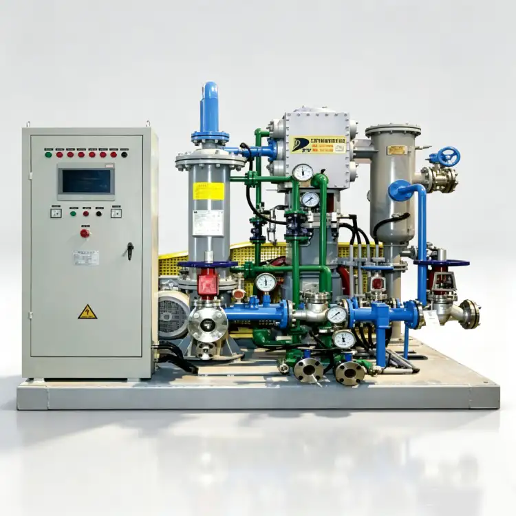
ZW-5/40 Nitrogen Compressor – Ultra-High-Pressure Oil-Free N2 Booster for 4.00 MPa Critical Process Applications
Engineered to deliver 5 m³/min at 4.00 MPa discharge pressure, the ZW-5/40 is a two-stage, three-row oil-free piston nitrogen compressor designed for ultra-high-pressure nitrogen injection, gas cylinder cascade filling, and demanding petrochemical process applications. Zero oil contamination, three-stage thermodynamic optimization, and built for continuous-duty operation at extreme pressure.
Productoverzicht
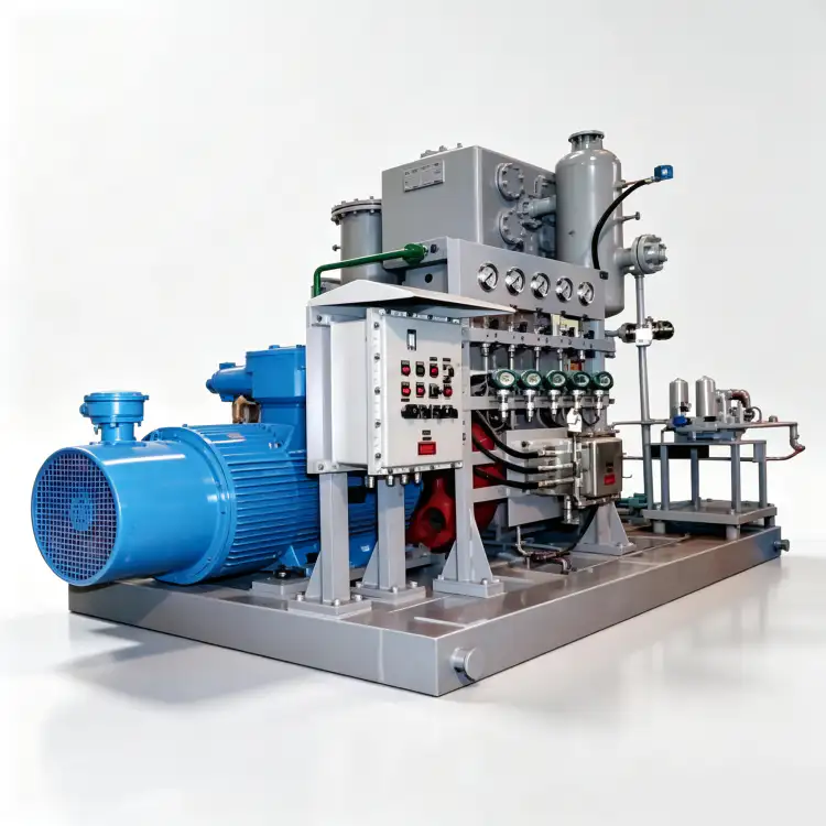
De ZW-5/40 nitrogen compressor represents the pinnacle of our oil-free piston compressor technology, engineered specifically for applications demanding both substantial flow capacity and ultra-high discharge pressure. With a rated capacity of 5 m³/min and an exceptional 4.00 MPa discharge pressure, this unit occupies the ultra-high-pressure segment of our industrial nitrogen compressor portfolio, serving the most demanding process applications in the global industrial gas market.
What distinguishes the ZW-5/40 from all conventional alternatives is its fully oil-free compression pathway combined with three-stage thermodynamic optimization. The piston rings and rider bands are fabricated from advanced self-lubricating PTFE composite materials specifically formulated for ultra-high-pressure service, operating without any hydrocarbon lubricants. This intrinsic oil-free characteristic ensures the nitrogen stream remains completely uncontaminated, achieving ISO 8573-1 Class 0 certification natively even at 4.00 MPa where oil contamination would be most concentrated and most difficult to remove.
The compressor employs a two-stage, three-row (二列三级) configuration that is thermodynamically essential for managing the extreme pressure ratio required to achieve 4.00 MPa discharge pressure. The three-row arrangement divides the compression work across three cylinders, with dedicated intercoolers between each stage maintaining gas temperatures within safe operating envelopes. The robust cast-iron frame with reinforced high-pressure cylinder sections and the precision-machined forged steel crankshaft are rated for a minimum service life of 100,000 hours under standard maintenance protocols in ultra-high-pressure service.
Technical Specifications – ZW-5/40
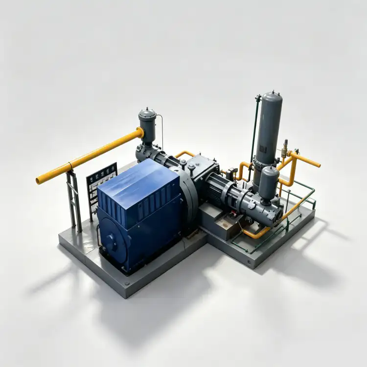
| Parameter | Value | Unit |
|---|---|---|
| Model | ZW-5/40 | – |
| Patroon | Two-stage, Three-row (二列三级) | – |
| Capaciteit | 5 | m³/min |
| Afvoerdruk | 4.00 | MPa |
| Compressor Size (L × W × H) | 1947 × 1900 × 2580 | mm |
| Gewicht | 3.97 | t |
| Stroom | 75 | kW |
| Spanning | 380 | V |
| Gasmedium | Nitrogen (N₂) | – |
| Lubrication | Olievrij | – |
* All specifications are rated at standard reference conditions (ISO 1217, Annex C). Actual performance may vary based on site altitude, ambient temperature, and inlet conditions.
Key Features & Engineering Advantages
1. Ultra-High-Pressure Oil-Free PTFE Sealing System
The ZW-5/40 employs a proprietary self-lubricating piston ring and rider band assembly manufactured from ultra-high-performance PTFE composites specifically developed for 4.00 MPa service. These rings are reinforced with high-strength glass fiber and bronze particulates to achieve a coefficient of friction below 0.05 without any external hydrocarbon lubrication. At 4.00 MPa discharge pressure, the partial pressure of oil vapor would be approximately 40 times higher than at 0.10 MPa, making oil contamination catastrophic and virtually impossible to remove downstream. The ZW-5/40’s native oil-free design eliminates this risk entirely, delivering ISO 8573-1 Class 0 compliance without any downstream filtration. The PTFE formulation is rated for continuous operation at temperatures up to 200°C, ensuring reliable sealing integrity under the extreme thermal stress of ultra-high-pressure compression.
2. Three-Stage Thermodynamic Optimization
De two-stage, three-row (二列三级) compression architecture of the ZW-5/40 is thermodynamically mandatory for achieving the 4.00 MPa discharge pressure target from typical inlet conditions of 0.05–0.10 MPa. The overall pressure ratio of approximately 40:1 to 80:1 is distributed across three compression cylinders, with each stage operating at a manageable pressure ratio of 3:1 to 4:1. Dedicated high-efficiency shell-and-tube intercoolers between each stage remove the substantial heat of compression, maintaining discharge temperatures below 160°C and preventing thermal degradation of the PTFE sealing elements. Without this three-stage approach, the discharge temperature would exceed 250°C, far beyond the safe operating limit of any oil-free sealing material. The staged design also improves volumetric efficiency by approximately 15% compared to two-stage alternatives at equivalent pressure ratios.
3. Reinforced High-Pressure Frame Construction
The main frame is cast from GG25 gray cast iron with substantially reinforced wall sections in the high-pressure cylinder area to withstand the mechanical stresses of 4.00 MPa peak pressures. The cylinder walls in the third (high-pressure) stage are approximately 40% thicker than standard low-pressure cylinders, with additional external ribbing to prevent distortion under pressure. The three-row opposed-cylinder arrangement provides excellent force balance, with the first and third stages opposing the second stage to minimize net inertial forces. The forged steel crankshaft is dynamically balanced to ISO 1940 G2.5 standards and features hardened bearing journals to withstand the increased bearing loads associated with high-pressure gas forces. The entire crankcase assembly is designed for a minimum burst pressure of 6.00 MPa, providing a 50% safety margin above the maximum operating pressure.
4. Standard 380V Industrial Motor with High-Torque Design
The ZW-5/40 is driven by a 75 kW, 380V, 50Hz three-phase induction motor conforming to IEC 60034-1 efficiency class IE3. The motor features a high-torque design specifically selected to handle the peak torque requirements of ultra-high-pressure compression, where the gas load on the pistons creates significant resistance during the compression stroke. The standard 380V configuration integrates directly into existing industrial distribution panels without requiring medium-voltage infrastructure, making the unit accessible to a wide range of facilities. The motor is coupled to the compressor through a heavy-duty flexible disc coupling that accommodates minor misalignment while transmitting the high torque required for 4.00 MPa operation.
Application Scenarios
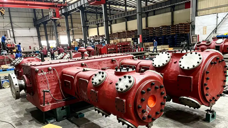
Ultra-High-Pressure Nitrogen Cylinder Cascade Filling
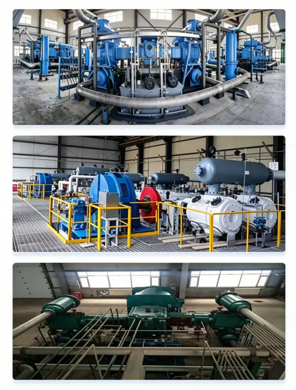
The ZW-5/40 is purpose-built for nitrogen cylinder cascade filling stations where gas must be compressed to 4.00 MPa for storage in high-pressure tube trailers or cylinder banks. The 4.00 MPa discharge pressure is the standard storage pressure for industrial nitrogen tube trailers, allowing efficient transportation of large nitrogen volumes to remote job sites, construction projects, and emergency response locations. The 5 m³/min capacity enables rapid filling of tube trailers, with a typical 3,000-liter tube trailer filling in approximately 10 hours. The oil-free design is absolutely critical for cylinder filling because any oil contamination would be trapped in the high-pressure storage system and delivered to end-users, potentially contaminating their processes and violating purity specifications.
Petrochemical Ultra-High-Pressure Nitrogen Injection
In petrochemical and refinery operations, the ZW-5/40 nitrogen compressor provides ultra-high-pressure nitrogen for emergency depressurization of high-pressure reactors, catalyst bed preservation during shutdown, and hydrostatic testing of process vessels rated to 3.20 MPa design pressure. The 4.00 MPa discharge pressure provides a 25% margin above the test pressure of typical Class 300 process piping and vessels, ensuring safe and effective pressure testing. The oil-free design is mandatory for petrochemical applications where nitrogen contacts catalyst beds or enters process streams that must remain completely hydrocarbon-free. Even trace oil contamination at 4.00 MPa would be concentrated enough to deactivate expensive catalysts and contaminate high-value product streams.
Oil & Gas Well Stimulation & Workover
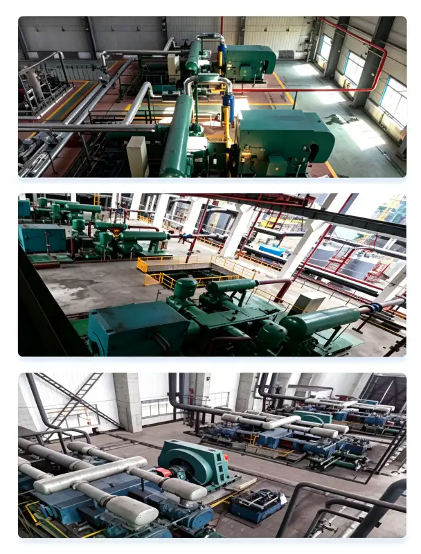
In upstream oil and gas operations, the ZW-5/40 supplies high-pressure nitrogen for nitrogen lift operations, well stimulation, and workover procedures. Nitrogen is injected into oil wells at high pressure to reduce the hydrostatic head of the fluid column, allowing reservoir fluids to flow to the surface. The 4.00 MPa discharge pressure is sufficient for nitrogen lift in wells with depths up to 2,000 meters, and the 5 m³/min capacity can support continuous nitrogen injection for extended workover campaigns. The oil-free design prevents contamination of formation fluids and ensures that the nitrogen does not introduce hydrocarbons into the reservoir that could alter wettability or damage the formation.
Aerospace & Defense High-Pressure Nitrogen Systems
Aerospace manufacturing and defense facilities require ultra-high-pressure nitrogen for hydraulic system testing, fuel tank inerting system validation, and spacecraft propulsion system ground support. The ZW-5/40’s 4.00 MPa discharge pressure is suitable for testing aircraft hydraulic systems rated to 21 MPa working pressure (using nitrogen as a safe test medium), and for filling ground support equipment used in spacecraft launch preparation. The oil-free certification ensures compliance with aerospace cleanliness standards (MIL-PRF-27401 and equivalent) that prohibit any hydrocarbon contamination in systems that will operate in the vacuum of space.
Material & Construction
The ZW-5/40 is constructed from premium materials selected for ultra-high-pressure nitrogen compatibility, extreme thermal resistance, and extended operational life:
| Component | Material | Specificatie |
|---|---|---|
| Cylinder Block (LP Stage) | Gray Cast Iron | GG25 / HT250, standard wall thickness |
| Cylinder Block (IP Stage) | Gray Cast Iron | GG25 / HT250, reinforced wall + ribbing |
| Cylinder Block (HP Stage) | Gray Cast Iron | GG25 / HT250, heavy-duty reinforced, 40% thicker walls |
| Crankshaft | Forged Alloy Steel | 42CrMo4, Q&T, hardened journals, ISO 1940 G2.5 |
| Piston Rings (All Stages) | PTFE-Glass-Bronze Composite | Ultra-high-pressure rated, self-lubricating, 200°C max |
| Rider Bands | PTFE Composite | Piston guidance, anti-scuffing, wear rate <0.03 mm/1000h |
| Valve Plates (All Stages) | Roestvrij staal | SS316, high-pressure concentric ring, reinforced springs |
| Intercoolers (2 units) | Carbon Steel Shell / SS316 Tubes | ASME VIII Div.1, 1.5× hydrotest, 30 min hold |
| Aftercooler | Carbon Steel Shell / SS316 Tubes | High-pressure finned tube, 32°C cooling water |
| High-Pressure Piping | Seamless Stainless Steel | SS316, ANSI Class 900 flanges, 100% X-ray tested |
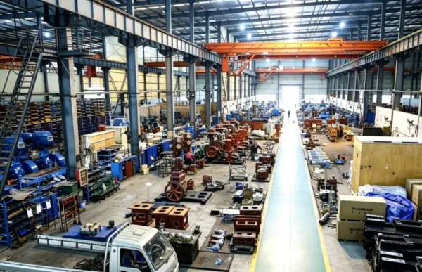
All pressure-bearing components are designed and fabricated in strict accordance with ASME BPVC Section VIII Division 1 or Chinese GB 150 standards. Every weld joint undergoes 100% radiographic inspection (RT) per ASME Section V, Article 2, and each completed pressure vessel is subjected to a hydrostatic pressure test at 1.5 times the MAWP for a minimum hold period of 30 minutes. High-pressure piping systems are fabricated from seamless SS316 with ANSI Class 900 flanged connections and 100% X-ray testing to ensure absolute leak-tight integrity at 4.00 MPa operating pressure.
Installation & Maintenance Guidelines
Foundation & Structural Requirements
The ZW-5/40 has a dry weight of 3.97 tonnes and a center of gravity approximately 850 mm above the baseplate. Despite the three-row design providing good force balance, the high-pressure operation generates substantial gas forces that require a reinforced concrete inertia block of 8–10 tonnes. The block must be mounted on heavy-duty elastomeric vibration isolators (natural frequency 6–8 Hz) to prevent vibration transmission. Minimum clearance requirements: 1.5 m on the non-drive side for valve access, 1.2 m on the drive side for motor maintenance, and 2.0 m overhead for crane access. The high-pressure discharge piping must be independently supported with spring hangers or rigid anchors to prevent vibration-induced fatigue at 4.00 MPa. A pressure relief valve rated at 110% of MAWP and a rupture disc rated at 120% of MAWP must be installed on the discharge line.
Cooling Water System Design
Cooling water demand is approximately 15 m³/h at an inlet temperature not exceeding 32°C. The water distribution circuit supplies the cylinder jackets and two intercoolers in parallel, with priority flow to the intercoolers. Given the extreme pressure ratio, intercooler performance is absolutely critical—if intercooler effectiveness drops below 80%, the discharge temperature will exceed the safe limit of PTFE materials. Water quality specifications: pH 6.5–8.5, total dissolved solids < 500 mg/L, chloride content < 30 mg/L (strict limit for SS316 tube corrosion prevention at high pressure), suspended solids < 20 mg/L, and total hardness < 250 mg/L as CaCO₃. A closed-loop cooling tower with full-stream filtration and chemical treatment is mandatory for reliable operation.
Preventive Maintenance Schedule
| Interval | Service Item | Action Required |
|---|---|---|
| Daily | Operational Inspection | Check vibration, abnormal noise, cooling water flow, all stage discharge temperatures and pressures |
| 200 hours | Valve Plate Inspection (HP Stage) | Inspect high-pressure stage valves for carbon deposits, spring fatigue, cracking, seat erosion |
| 500 hours | Valve Plate Inspection (All Stages) | Inspect all stage valves, measure spring free length, check for plate warping |
| 1,000 hours | Piston Ring Wear Assessment | Measure all stage ring groove clearances; replace HP stage rings if > 0.15 mm |
| 2,500 hours | Intermediate Overhaul | Replace all piston rings, rider bands, and valve plate assemblies across all stages |
| 5,000 hours | Major Overhaul | Inspect crankshaft journals, measure all bearing clearances, replace bearings if >0.06 mm |
The oil-free design of the ZW-5/40 eliminates the entire category of oil-related maintenance tasks. However, the ultra-high-pressure operation demands more frequent attention to valve plates and piston rings than lower-pressure models. The high-pressure stage (third stage) valve plates are the most stressed components and require inspection every 200 hours during the first 1,000 hours of operation to establish baseline wear patterns. Once baseline wear rates are established, the inspection interval can be extended based on actual condition monitoring data.

Compliance & Safety Certifications
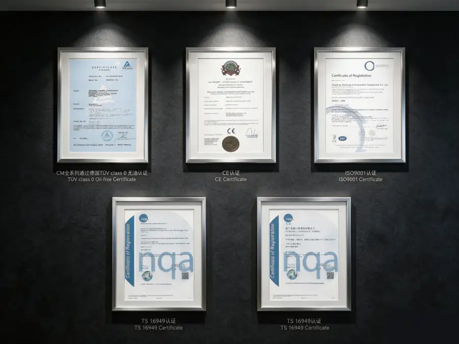
The ZW-5/40 nitrogen compressor is designed, manufactured, and tested to meet or exceed the following international standards and regulatory frameworks:
ASME BPVC Section VIII Div.1, GB 150-2011, PED 2014/68/EU Module H (Full Quality Assurance)
IEC 60034-1 (IE3 efficiency), IEC 60204-1, ISO 12100 machinery safety
ISO 8573-1 Class 0 (Oil Content), independently tested by TÜV Rheinland at 4.00 MPa
ISO 9001:2015, ISO 14001:2015, OHSAS 18001/ISO 45001
Nitrogen is a simple asphyxiant gas. At 4.00 MPa discharge pressure, the potential energy stored in the compressed gas and the risk of catastrophic release are extremely high. All ZW-5/40 installations must incorporate: (1) Continuous oxygen deficiency monitoring in the compressor room and all adjacent areas; (2) Pressure relief valves rated at 110% of MAWP on all pressure vessels and the discharge line; (3) Rupture discs rated at 120% of MAWP as secondary protection; (4) Emergency isolation valves on inlet and discharge lines with remote actuation capability; (5) Ventilation maintaining ambient oxygen above 19.5% per OSHA 29 CFR 1910.146; (6) Emergency shutdown at 19.5% O₂ (alarm) and 18.0% O₂ (hard isolation). Personnel must complete high-pressure gas safety training and wear appropriate PPE before operating or maintaining this equipment. High-pressure piping must be protected from mechanical damage and clearly marked with pressure ratings.
Performance & Efficiency Analysis
The ZW-5/40 achieves a specific power consumption of approximately 15.00 kW per m³/min of nitrogen delivered at 4.00 MPa discharge pressure. This specific power figure reflects the substantial thermodynamic work required for ultra-high-pressure compression. Within the ultra-high-pressure oil-free compressor segment (discharge pressure >3.00 MPa), this efficiency is highly competitive. For comparison, oil-lubricated reciprocating compressors in similar ultra-high-pressure applications typically consume 16–18 kW/m³/min, while diaphragm compressors (often selected for oil-free ultra-high-pressure service) may exceed 20 kW/m³/min with significantly lower capacity.
Over an 8,000-hour annual operating cycle, the ZW-5/40’s efficiency advantage versus less efficient alternatives yields approximately 40,000–120,000 kWh of annual energy savings. At $0.08/kWh, this represents $3,200–$9,600 in direct electricity cost reduction per year. However, the primary economic justification for the ZW-5/40 is typically the elimination of oil-related consumables and the impossibility of downstream oil removal at 4.00 MPa. At this pressure, oil-filtration systems become prohibitively expensive, maintenance-intensive, and unreliable. The total cost of ownership for ultra-high-pressure nitrogen compression is reduced by an estimated 35–45% over a 10-year operational life when oil-free operation is compared to lubricated systems with attempted downstream purification.
The three-stage design also provides a significant efficiency advantage over two-stage alternatives at this pressure level. By dividing the overall pressure ratio across three stages with intercooling, the ZW-5/40 achieves an isothermal efficiency approximately 12% higher than an equivalent two-stage compressor, translating to lower discharge temperatures, reduced cooling water consumption, and extended seal life.
Customization & OEM Capabilities
We offer specialized customization options to adapt the ZW-5/40 to the demanding requirements of ultra-high-pressure applications:
- Skid-Mounted Turnkey Packages: Pre-assembled compressor, motor, dual intercoolers, aftercooler, high-pressure discharge piping with ANSI Class 900 flanges, instrumentation, and control panel on a structural steel skid. All pressure systems are factory hydrotested to 6.00 MPa before shipment.
- Hazardous Area Configurations: ATEX Zone 2 and IECEx compliant motor and electrical enclosures with intrinsically safe instrumentation. Integrated gas detection, automatic ventilation, and emergency isolation systems.
- Advanced Safety & Control Systems: Siemens S7-1200 PLC with redundant safety PLC for emergency shutdown functions, 10-inch HMI touchscreen, remote monitoring via Modbus TCP/IP or OPC-UA. Automatic pressure relief sequencing, emergency isolation valve control, and high-temperature shutdown interlocks on all three stages.
- Environmental Protection: C5-M marine-grade coatings for coastal installations; tropicalized electrical components for 55°C ambient; IP54-rated acoustic enclosures with blast-resistant panels for high-pressure safety.
- OEM & Private Label: Custom paint colors, branded nameplates, and localized documentation packages for gas equipment distributors and system integrators serving oil & gas and aerospace markets.
Custom configurations are available from MOQ 1 unit. Engineering review and proposal generation typically require 7–10 business days due to the complexity of ultra-high-pressure system design. Standard delivery time is 14–16 weeks; expedited delivery within 12 weeks is available for qualifying orders.
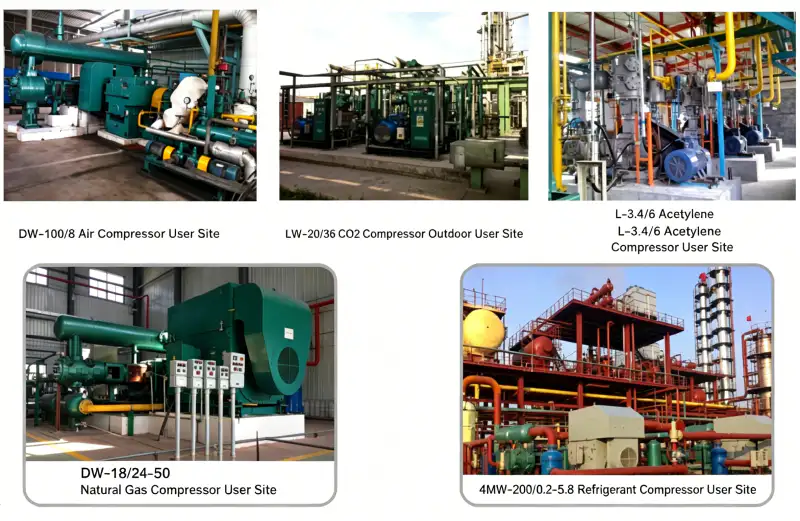
Case Study: Industrial Gas Cylinder Filling Station Upgrade
Client: A major industrial gas distributor in the Middle East operating a nitrogen cylinder and tube trailer filling station
Challenge: The client was operating an aging oil-lubricated high-pressure compressor (European brand, 20 years in service) for filling nitrogen tube trailers to 4.00 MPa. Oil contamination in the filled trailers reached 2.8 mg/m³, causing repeated customer complaints from semiconductor and pharmaceutical clients who required ISO 8573-1 Class 0 nitrogen. The oil was also degrading the high-pressure storage system, requiring internal cleaning and recoating every 18 months at a cost of $45,000 per cleaning cycle. The compressor was experiencing frequent valve failures due to the high pressure ratio, with unplanned downtime averaging 120 hours per year.
Solution: We supplied a ZW-5/40 oil-free nitrogen compressor as the primary filling compressor, configured on a custom skid with integrated dual intercoolers, aftercooler, high-pressure discharge piping with ANSI Class 900 flanges, and a Siemens S7-1200 PLC with redundant safety PLC. The three-stage design reduced the pressure ratio per stage compared to the replaced two-stage compressor, improving reliability. The oil-free design eliminated the need for any downstream purification.
Quantified Results After 24 Months:
- Nitrogen oil content in filled trailers: Reduced from 2.8 mg/m³ to <0.01 mg/m³, achieving ISO 8573-1 Class 0
- Storage system cleaning cycles: Eliminated completely, saving $45,000 every 18 months
- Customer complaints: Zero since commissioning; won two new semiconductor contracts worth $320,000/year
- Unplanned downtime: Reduced from 120 hours/year to 8 hours/year (scheduled maintenance only)
- Valve replacement frequency: Reduced by 60% due to lower per-stage pressure ratio
- Payback period: 2.3 years including new contract revenue
“The ZW-5/40 has completely transformed our high-pressure filling operation. We can now guarantee Class 0 nitrogen to every customer, our maintenance team spends 80% less time on emergency repairs, and we’ve won contracts that were previously impossible due to our oil contamination issues. The three-stage design is noticeably more reliable than our old two-stage compressor.” — Operations Director, Industrial Gas Distributor
FAQ & Selection Guide
Related Products & Solutions
DW Series High-Pressure Nitrogen Compressors
Designed for discharge pressures from 0.40 MPa to 2.00 MPa, the DW series covers nitrogen injection, high-pressure pipeline boosting, and chemical synthesis. Capacities from 2 to 130 m³/min with multi-stage configurations.
ZW Series Multi-Stage Oil-Free Compressors
Vertical and horizontal multi-stage oil-free compressors for oxygen, nitrogen, hydrogen, and specialty gases. Discharge pressures up to 9.00 MPa with four-stage and five-stage configurations.
4MW Series Ultra-High-Pressure Compressors
Four-row, multi-stage ultra-high-pressure compressors (3.00–9.00 MPa) for large-scale nitrogen injection, gas liquefaction, and specialty gas applications. Capacities from 50 to 200 m³/min.
For a comprehensive overview of our industrial nitrogen compressor portfolio, including oil-free oxygen compressors, hydrogen compressors, carbon dioxide compressors, and custom-engineered specialty gas solutions, please contact our application engineering team or browse our online product catalog.
Ready to Upgrade Your Ultra-High-Pressure Nitrogen System?
Our application engineers are standing by to evaluate your nitrogen flow requirements, inlet conditions, discharge pressure targets, and integration constraints. We provide complimentary technical proposals, foundation layout drawings, piping and instrumentation diagrams (P&IDs), safety system designs, and detailed total cost of ownership (TCO) analyses within 48 hours of receiving your inquiry.
Email: [email protected] | Response within 24 hours