
Азот мөлшері аз компрессор ағынын диагностикалау
Алдымен ағын көрсеткішін қалыпқа келтіріңіз, содан кейін компрессордың сыйымдылығын бағаламас бұрын кіріс шектеуін, сору жағдайын, жылдамдығын, түсіруді, ағып кетуді, клапанның денсаулығын және қоршаған ортаның өзгерістерін тексеріңіз.
Төмен ағынды шағымды қате диагноз қою оңай, себебі азот ағыны нақты м3/сағ, Нм3/сағ, См3/сағ, масса ағыны немесе басқа анықтамалық база ретінде көрсетілуі мүмкін. Бірдей масса ағынының әртүрлі қысым мен температурада әртүрлі көлемдік мәндері болады. Компрессорды ашпас бұрын, өлшенген мән мен күтілетін мән бірдей анықтамалық шартты қолданатынын растаңыз. Содан кейін сору қысымын, сору температурасын, жылдамдығын, басқару күйін және ағынның төменгі ағысындағы қысымды тексеріңіз. Лас сору сүзгісі, генератор өнімінің төмен қысымы, жылырақ кіріс газы, жартылай белсенді түсіргіш, ішкі клапанның ағып кетуі, сақинаның үрленуі немесе сыртқы ағып кету жеткізілетін анықтамалық ағынды азайтуы мүмкін. Себебіне жетудің ең жылдам жолы - іске қосу деректерімен салыстырғанда қайталанатын өнімділік суреті.
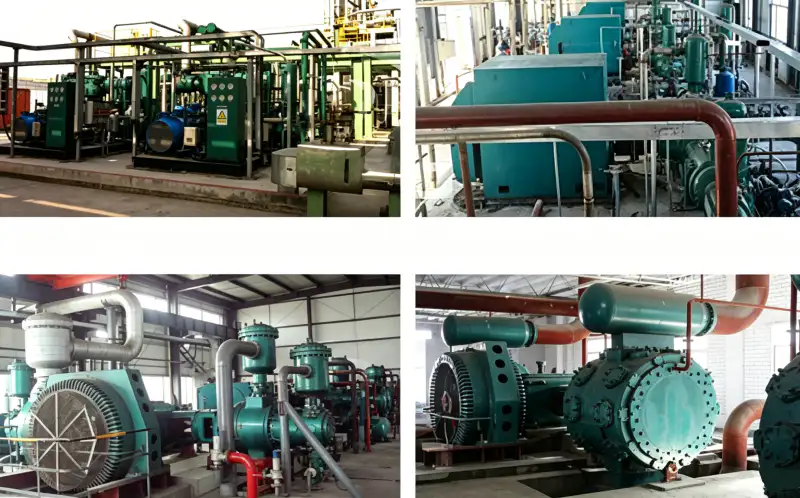
Төмен ағынды айнымалылар
- нақты ағын
- Өлшеуіш газды өлшейтін қысым мен температурадағы көлемдік ағын, егер құрал оны іштей басқа негізге түрлендірмесе.
- сілтеме ағыны
- Ағын белгіленген стандартты немесе қалыпты қысым мен температураға түрлендіріледі, сондықтан сыйымдылықты салыстыру бірдей негізді пайдаланады.
- сорғыш сүзгі
- Кіріс сүзгісі немесе сүзгісі ластану жиналған кезде қысымның төмендеуі компрессорды істен шығаруы мүмкін.
- клапанның жағдайы
- Цилиндрді тиімді толтыру мен жеткізуді анықтайтын компрессордың сору және шығару клапандарының тығыздалуы мен динамикалық жағдайы.
- ағып кету
- Ішкі айналма жол, сақиналар, тығыздау, желдеткіштер, қосылыстар, дренаждар, жеңілдету құрылғылары немесе төменгі ағынды желі арқылы жоғалатын газ.
- жылдамдық
- Компрессордың нақты айналу жылдамдығы, ол ығысу жылдамдығына әсер етеді және бекітілген жұмыс диапазонында қалуы керек.
1. Өлшенген және күтілетін ағынды бірдей негізге қойыңыз
Ағын өлшегіштің конфигурациясы мен құжаттамасын оқыңыз. Нақты көлемді, қалыпты көлемді, стандартты көлемді немесе массаны көрсететінін жазып алыңыз. Анықтамалық қысым мен температураны және газ құрамын өтеу қолданылғанын жазып алыңыз. Жеткізушінің қуатын тапшылықты есептемес бұрын сол негізге түрлендіріңіз. Нақты жоғары қысымды желі көлемін тікелей Nm3/сағ рейтингімен салыстырмаңыз.
Есептегіштің жұмысын және орнатылуын тексеріңіз. Тікелей жұмыс талаптары, қысым мен температураны өтеу, диапазонның өзгеруі, сенсордың ластануы немесе газ конфигурациясының өзгеруі көрсеткіштерге әсер етуі мүмкін. Егер ағын мәні қабылдағыштың толтыру жылдамдығымен және технологиялық шығынмен қайшы келсе, компрессордың жоғалған қуатын анықтамас бұрын тәуелсіз әдіспен тексеріңіз.
2. Толық тарту кезінде кіріс шектеуін және сору қысымын тексеріңіз
Компрессор сынақ жүктемесінде болған кезде сору сүзгісінің немесе шектеуші компоненттердің алдында және кейінгі қысымды өлшеңіз. Таза көрінетін сүзгіде қысымның дифференциалды қысымы әлі де жоғары болуы мүмкін. Күшейткіштің кіріс қысымын жоғары ағынды өнім қабылдағышымен салыстырыңыз. Егер айырмашылық ағынмен бірге артса, сүзгі элементтерін, клапандарды, құбырларды, икемді қосқыштарды және кез келген ұсақ диаметрлі бөлікті тексеріңіз.
Сондай-ақ, көз қысымын тексеріңіз. Жергілікті азот генераторы жоғары сұраныс кезінде өнімнің қысымын төмендетуі мүмкін, бұл компрессордың ығысуы өзгермесе де, күшейткіш масса ағынының төмендеуіне әкелуі мүмкін. Көз сыйымдылығын жергілікті кіріс шектеуінен бөлу үшін тренд қабылдағышының қысымы мен компрессордың сорғышын бірге қолданыңыз.
Бұл шешімді сайттың шешімімен салыстырып тексеруге де болады азот компрессорының төмен ағыны Жоба деректер парағы жарияланғанға дейінгі ақпарат. Мұндағы кері тексеру n2 компрессорының ағыны неге күтілгеннен төмен екеніне байланысты.
3. Жылдамдықты, жүктемені және сыйымдылықты басқару құрылғыларын тексеріңіз
Нақты айналу жылдамдығын өлшеңіз немесе тексерілген жетек кері байланысын оқыңыз. VFD шегі, қозғалтқыш мәселесі, белдіктің сырғанағы немесе басқару қақпағы ығысуды азайтуы мүмкін. Түсіргіштердің, саңылау қалталарының, айналма жолдардың немесе қайта өңдеу клапандарының өнімділікті салыстыру кезінде қабылданған күйде екеніне көз жеткізіңіз. Компрессор үздіксіз жұмыс істей беретіндіктен, ішінара түсіру көбінесе назардан тыс қалады.
Егер сыйымдылықты басқару қабылдағыш қысымын пайдаланса, таратқыштың калибрлеуін және орнатылған мәндерін тексеріңіз. Қате жоғары қысым көрсеткіші компрессорды ертерек босатуға бұйрық бере алады. Төмен ағынды кезең механикалық тозумен емес, басқару ауысуларымен сәйкес келетінін білу үшін оқиға тарихын қарап шығыңыз.
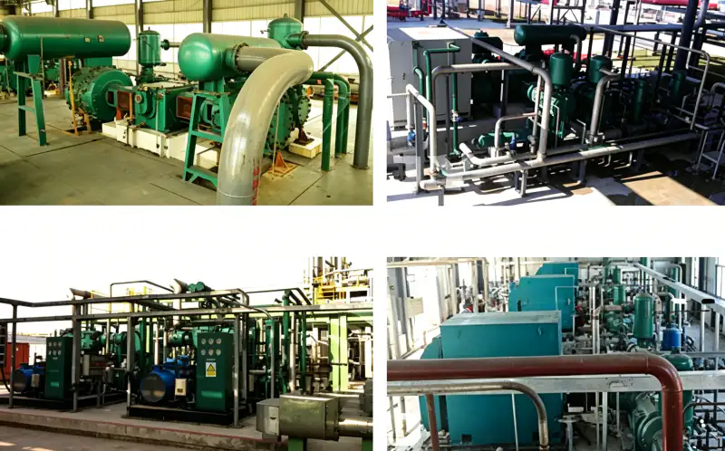
4. Кіріс температурасы мен жұмыс қысымын бастапқы деңгеймен салыстырыңыз
Жылы сору газының тығыздығы азырақ, сондықтан сол көлемде азот массасы аз болады. Егер сыйымдылық анықтамалық ағын ретінде көрсетілсе, ыстық компрессор бөлмесі немесе ыстық генератор өнімі жеткізілетін анықтамалық ағынды азайтуы мүмкін. Маусымдық өзгерісті тозу ретінде қарастырудың орнына, сору температурасын жазып алып, салыстыруды түзетіңіз.
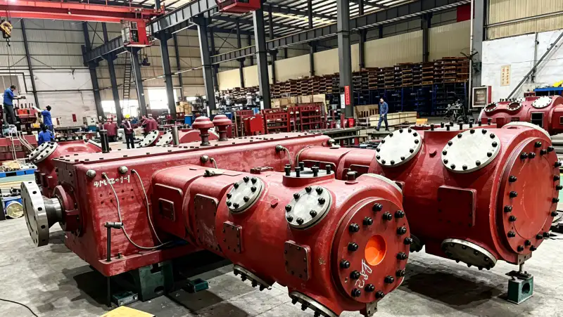
Жоғары шығару қысымы немесе төмен сору қысымы компрессордың көлемдік тиімділігі мен ағып кету мінез-құлқын да өзгертеді. Нақты қысым қатынасы үшін жеткізушінің өнімділік деректерін пайдаланыңыз. Бір номиналды нүктеде сыналған машинаның сол сыйымдылықты түзетусіз айтарлықтай басқа қатынаста қайталайтыны күтілмеуі керек.
5. Ішкі ағып кетуді анықтау үшін қысым-температура үлгілерін пайдаланыңыз
Сору немесе шығару клапандарының ағып кетуі тиімді өнімділікті төмендетеді және көбінесе сатылы қысым мен температураны өзгертеді. Сақинаның ағып кетуі үрлеуді арттыра отырып немесе желдеткіштің жұмысын өзгерте отырып, беруді төмендетуі мүмкін. Қаптаманың ағып кетуі белгіленген шыбық тәрізді тығыздау желдеткіштерінде немесе сыртқы ағып кету нүктелерінде пайда болады. Бастапқы сызықпен бірдей жүктемедегі сатылы мәндерді жазып алыңыз және бір реттік ыстық көрсеткіштің орнына үлгіні іздеңіз.
Клапанның ағып кетуіне күдік бар екенін бөлшектемес бұрын өндіруші бекіткен сынақпен растаңыз. Сақина немесе қаптама мәселелері үшін өнімділік деректерін ағып кету үрдісімен және тексерумен біріктіріңіз. Қай механизмнің өзгергенін анықтамай, барлық тозу бөлшектерін ауыстыру қайталануының алдын алуды қиындатады.
Процесс қабығы тұрақты болған кезде, сайттың азот компрессорын өндіруші бетінде келесі таңдау қадамы үшін практикалық жабдыққа сілтеме берілген. Мұндағы айқаспалы тексеру n2 компрессорының ағыны неге күтілгеннен төмен екеніне байланысты.
6. Сыртқы және төменгі ағыстағы газ шығындарын сандық бағалау
Компрессор ағын өлшегіші қалыпты берілісті көрсетуі мүмкін, ал пайдаланушы газды аз көреді, себебі коллектордың ағып кетуі, дренаждан өту, сақтандырғыш клапан, ашық үрлеу немесе реттегіш азотты тұтынады. Керісінше, ағып кетуден жоғары ағын өлшегіші компрессордың сыйымдылығын жоғары етіп көрсетуі мүмкін, ал пайдалы ағын төмен. Сынақ шекарасын белгілеп, әрбір шығысты ескеріңіз.
Себебін жойғаннан кейін, тұрақты сору және шығару жағдайларымен бақыланатын сыйымдылық сынағын қайталаңыз. Анықтамалық ағынды, нақты ағын негізін, жылдамдықты, қысымды, температураны, кезең деректерін және ағып кету көрсеткіштерін жазып алыңыз. Бұл жаңа тексерілген базалық деңгейге айналады және болашақ өзгерістердің процеске немесе машинаға негізделгенін анықтауға көмектеседі.
Төмен ағынды диагностикалық үстел
| Тауар | Инженерлік сұрақ | Тексеру немесе шешім қабылдау сигналы |
|---|---|---|
| Ағын негізі | Есептегіш пен күтілетін қуат бірдей анықтамалық шартты пайдалана ма? | Өнімділік шығыны есептелмес бұрын мәндер қалыпқа келтіріледі. |
| Кіріс жолы | Сүзгілер мен құбырлардан кейін компрессорға қандай қысым жетеді? | Сору дифференциалы таза бастапқы сызыққа жақын қалады. |
| Басқару күйі | Нақты жылдамдық пен жүктеме сынақ болжамына тең бе? | Жетек пен түсіргіштің кері байланысы толық жоспарланған сыйымдылықты растайды. |
| Ағып кету | Азоттың жеткізілуі қайдан шығуы немесе айналып өтуі мүмкін? | Кезең деректері және шекаралық ағып кетуді тексеру шығынды анықтайды. |
| Басқа инженер шешімді қайталай алатындай етіп, соңғы негізді RFQ-ға, іске қосу файлына немесе техникалық қызмет көрсету жазбасына жазып алыңыз. | ||
Жобаны тексеру жұмыс парағы
Жұмыс тапсырысын жаппас бұрын, «Ағын бірлігін, қалыпты/стандартты анықтамалық жағдайды және өлшеуіш конфигурациясын растаңыз» дегенді дәлелдемелерге сәйкес келетіндей етіп жасаңыз. Нақты ағын үшін анықтамалық нүктені және бірлікті немесе физикалық жағдайды жазып алыңыз; сору сүзгісі үшін жүйенің үйлесімді жұмыс істеп тұрғанын растайтын салыстыру нүктесін жазып алыңыз. Екі бақылауды да «ағын негізін тексерумен» және нақты жүктемемен немесе жұмыс режиміне байланыстырыңыз. Орналасқан жері мен күйі жоқ мәнді кейінірек қайта пайдалану қиын. Тексеру сәйкессіздікті анықтаған жағдайда, оны тудырған шектеуді, басқару күйін, компонент жағдайын немесе жобалау болжамын түзетіңіз, содан кейін жөндеу болжамды емес, дәлелденгендей етіп сол бақылауды қайталаңыз.
«Кіріс шектеуін тексеруді» шағын іске қосу эксперименті ретінде қарастырыңыз. Бастапқы күйді анықтаңыз, анықтамалық ағынды бақылаңыз, бекітілген сынақ үшін қажетті айнымалыны ғана өзгертіңіз және клапан жағдайындағы жауапты бақылаңыз. «Толық сынақ ағынында сору сүзгісінің дифференциалын және компрессор-кіріс қысымын өлшеу» әрекеті бастапқы күйдің, араласудың, соңғы күйдің және кез келген дабыл немесе басқару реакциясының жазбасын қалдыруы керек. Бұл бірнеше компонент бірдей симптомды тудыруы мүмкін болған кезде пайдалы. Бір уақытта бір факторды өзгертіп, компрессорды бекітілген конвертте сақтау арқылы топ себепті кездейсоқтықтан ажырата алады және жауапты емес жабдықты ауыстырудан аулақ бола алады.
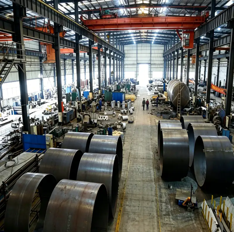
Ұзақ мерзімді сенімділік үшін «Бастапқы қысымды, сору температурасын, жылдамдығын және сыйымдылықты басқару күйін тексеріңіз» функциясын сору сүзгісінің негізгі сызығымен байланыстырыңыз. Орнату таза, тұрақты және жұмыс істеп тұрғаны белгілі болған кезде негізгі сызықты жазып алыңыз, содан кейін ағып кетуді және жұмыс жүктемесін қосыңыз, сонда кейінгі көрсеткіштерді қалыпқа келтіруге болады. «Жылдамдықты және басқару күйін растау» шолу тұжырымдамасында абсолютті мән дабылға жетпеген кезде де зерттеу үшін анықталған триггер болуы керек. Қайталанатын негізгі сызықтан біртіндеп ауытқу көбінесе бір оқшауланған көрсеткішке қарағанда көбірек ескерту береді. Егер процесс конфигурациясы өзгерсе, әртүрлі жұмыс күйлерін салыстырудың орнына жаңа құжатталған негізгі сызық жасаңыз.
Инженерлік шолу кезінде клапанның жағдайы мен жылдамдығымен байланысты физикалық жолды бақылау арқылы «ағып кетуді тексеру» деген болжамға күмән келтіріңіз. Газдың, жылудың, күштің, басқару сигналының немесе ағып кету жолын көзден тағайындалған жерге дейін қадағалаңыз және нәтижені өзгерте алатын әрбір компонентті анықтаңыз. Содан кейін шешім қабылданған жерде, ең ыңғайлы өлшеуіште емес, «Нақты қысым коэффициентін жеткізушінің өнімділік негізімен салыстырыңыз» деп толтырыңыз. Кез келген қысымның төмендеуін, температура айырмашылығын, басқару кідірісін немесе мінез-құлықты түсіндіретін тексеру нәтижесін жазып алыңыз. Бұл жолға негізделген тексеру жергілікті өлшемдердің жүйелік контекстсіз түсіндірілуіне жол бермейді.
Сатып алуды үйлестіру үшін осында сипатталған талапты сайттың талабымен салыстырыңыз көп сатылы азот компрессоры жалпы компрессор рейтингіне сүйенудің орнына ұсынады. Мұндағы айқаспалы тексеру n2 компрессорының ағыны неге күтілгеннен төмен екеніне байланысты.
«Ішкі себептерді тексеру үшін саты қысымын, температурасын, желдеткішті және ағып кету үрдістерін пайдаланыңыз» тексеруін болашақ ақаулықтарды зерттеу кезінде пайдалануға болатындай етіп жасаңыз. Ағып кетуді, нақты ағынды, компрессордың күйін, сұраныс күйін және бақылау уақытын бір жазбада жазып алыңыз. Сол жазбаны «клапандарды тексеру» жобалық мақсатымен байланыстырыңыз және қандай сызба, нұсқаулық, технологиялық сипаттама немесе калибрленген құрал қабылдауды белгілегенін ескеріңіз. Егер көрсеткіш қалыпты болса, ол анықтамалық мәнге айналады. Егер ол қалыптан тыс болса, түзету әрекетін құжаттап, сол жағдайда қайта тексеріңіз. Бірізді жазбалар қысымды, жылдамдықты, температура шектеулерін немесе байланыссыз параметрлерді арттыру арқылы түсініксіз мәселені өтеуге деген азғыруды азайтады.
Оның салдары пайда болатын шекарада «қоршаған орта жағдайларын салыстырыңыз» дегенді тексеріңіз. Оның көзіндегі жылдамдықты және қабылдау жағындағы анықтамалық ағынды бақылаңыз, содан кейін тиісті ағын мен қысым тұрақты болған кезде «Түзетуден кейін басқарылатын қалыпқа келтірілген ағын сынағын қайталаңыз және бастапқы сызықты сақтаңыз» дегенді орындаңыз. Қалыпты процестің өзгеруін жабдықтың тозуынан ажырату үшін жеткілікті контекст жазып алыңыз. Нақты қабылдау шектері таңдалған модельге байланысты болған кезде, өндірушінің ағымдағы құжаттамасын немесе бекітілген жоба сипаттамасын пайдаланыңыз. Қызмет ұқсас естілгендіктен ғана басқа компрессордан мәнді ауыстырмаңыз. Шекарадан шекараға дейінгі жазба кейінірек ақаулықтарды жоюды әлдеқайда жылдамдатады.
Қауіпсіздік және тексеру шекарасы
Ағынды сынау персоналды қысымды газға, айналмалы жабдыққа, ыстық компоненттерге және азот шығарындыларына ұшыратуы мүмкін. Толық ағынды сынақ алу үшін қауіпсіз емес желдету жолдарын жасамаңыз. Бекітілген сынақ қосылымдары мен оқшаулау шекараларын пайдаланыңыз. Сүзгілерді, клапандарды немесе цилиндрлерді ашу үшін құлыптау, қысымды төмендету және нөлдік энергияны тексеру қажет. Компрессордың жылдамдығы мен қысымы таңдалған машинаның бекітілген конвертінде қалуы керек.
Төмен ағынды сынақ тізбегі
- Ағын бірлігін, қалыпты/стандартты анықтамалық жағдайды және өлшеуіш конфигурациясын растаңыз.
- Толық сынақ ағынында сору сүзгісінің дифференциалын және компрессордың кіріс қысымын өлшеңіз.
- Бастапқы қысымды, сору температурасын, жылдамдығын және сыйымдылықты басқару күйін тексеріңіз.
- Нақты қысым коэффициентін жеткізушінің өнімділік негізімен салыстырыңыз.
- Ішкі себептерді тексеру үшін сатыдағы қысымды, температураны, желдеткішті және ағып кету үрдістерін пайдаланыңыз.
- Түзетуден кейін бақыланатын қалыпқа келтірілген ағын сынағын қайталаңыз және бастапқы сызықты сақтаңыз.
Компрессор ағыны туралы сұрақтар
Неліктен ыстық күні компрессор жылдамдығы бірдей болғанның өзінде Нм3/сағ төмендеді?
Ыстық сору газының тығыздығы азырақ, сондықтан бірдей ығысу массасы аз болуы мүмкін. Өлшенген сору температурасы мен қысымындағы нормаланған сыйымдылықты салыстырыңыз.
Лас сүзгі төмен сору қысымын тудырмай ағынды азайта ала ма?
Иә, егер қысымды өлшеу сүзгіден жоғары болса немесе төмендеу орташа болса. Жүктеме кезінде нақты шектеу бойынша айырмашылықты өлшеңіз.
Егер ағын төмен болса, бірақ барлық деңгейдегі қысым қалыпты болып көрінсе ше?
Ішкі тозуды болжамдамас бұрын, өлшеуіштің негізін және калибрлеуін, нақты жылдамдығын, сору тығыздығын, сыртқы ағып кетуді және күтілетін өнімділік нүктесінің ағымдағы разряд қысымына сәйкес келетінін тексеріңіз.
Сыйымдылықты диагностикалау ережесі
Алдымен N2 компрессорының төмен ағынын жалпы анықтамалық негізде дәлелдеу керек. Содан кейін кіріс қысымын, температураны, жылдамдықты, түсіруді, қысым қатынасын, ішкі ағып кетуді және сыртқы сұранысты зерттеңіз. Қалыптандырылған өнімділік суреті маусымдық немесе аспаптардың өзгерістерін механикалық ақаулықпен шатастыруға жол бермейді.

























