
Size storage from gas inventory between two pressure limits
A nitrogen receiver should cover a defined demand imbalance or cycling objective; vessel volume by itself does not describe usable storage.
A nitrogen buffer tank stores gas by allowing pressure to rise above a lower operating limit. The usable inventory is the difference in gas content between the chosen high and low absolute pressures, not simply the geometric vessel volume. To size a receiver for a peak event, first define downstream demand, compressor or generator supply during the event, event duration, allowable pressure drop and gas temperature assumption. The receiver must supply only the deficit between demand and ongoing production. For a simple isothermal ideal-gas estimate, normalized usable inventory is proportional to vessel volume multiplied by the difference between high and low absolute pressure, then corrected to the chosen reference pressure and temperature. Real systems may require compressibility and temperature corrections. A second sizing objective is compressor cycling: enough receiver volume can lengthen the time between load and unload or start and stop events. These two objectives—peak support and cycling control—should be evaluated separately because the controlling pressure band and time scale may differ.
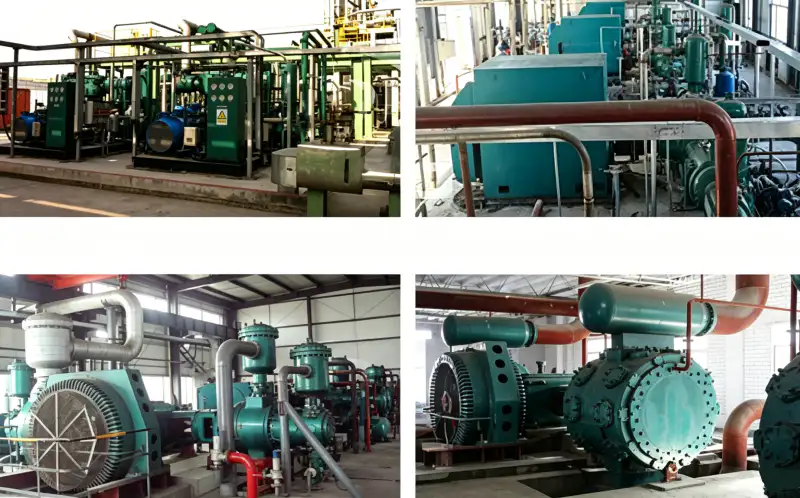
Receiver-sizing variables
- receiver volume
- Internal vessel volume available to store nitrogen gas.
- high pressure setpoint
- Upper receiver operating pressure at which the compressor may unload, slow or stop.
- low pressure setpoint
- Lower pressure at which capacity increases or the compressor restarts, while still meeting the process minimum.
- peak demand
- Maximum nitrogen consumption during the defined event, including its duration.
- compressor capacity
- Nitrogen flow the compressor continues to deliver while receiver pressure is falling during the event.
- usable gas inventory
- Difference in gas content between high and low receiver pressure expressed on the project reference basis.
1. Start with the demand deficit, not a tank rule of thumb
Create a time segment for the peak. If the process consumes 600 units of normalized flow while the compressor supplies 400, the receiver only needs to make up the 200-unit deficit for the event duration, not the full 600. If the compressor changes capacity as suction or discharge pressure changes, use a conservative supply estimate or integrate the actual capacity profile. For repeated peaks, include the time available for the receiver to recover between events. A tank large enough for one purge may still fail if the next purge starts before pressure is restored.
2. Choose the high and low pressure limits from the process and controls
The low receiver pressure must remain high enough to supply the downstream user after piping and control-valve losses. The high pressure must remain within the vessel, compressor and downstream equipment design and should fit the control strategy. A wider pressure band stores more usable gas in the same vessel, but it also changes compressor discharge ratio and may expose the process to greater regulator duty. Do not expand the pressure band beyond approved equipment limits merely to reduce vessel size. The process minimum, compressor setpoints and pressure protection need to be designed together.
3. Use absolute pressure in the inventory equation
For an isothermal ideal-gas screen, gas amount is proportional to P_abs V/T. Usable inventory between two pressures is therefore proportional to V(P_high_abs – P_low_abs) at roughly constant temperature. To express that inventory as normal cubic metres, apply the reference pressure and temperature ratio. If receiver temperature changes materially during fast filling or withdrawal, an isothermal assumption may not be accurate enough. High-pressure service may also need a real-gas compressibility correction. State the assumption so the sizing can be refined without losing the original logic.
Use the site’s nitrogen buffer tank sizing resource as a second check when translating this requirement into a compressor specification. The cross-check here is tied to size nitrogen buffer tank peak demand compressor.
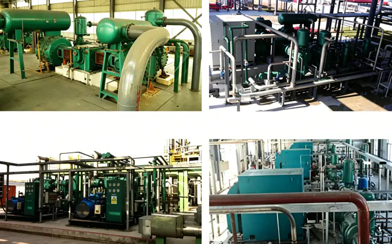
4. Check compressor cycling as a separate calculation
A receiver can reduce the frequency of starts or load-unload events by increasing the amount of gas that must be consumed before pressure crosses the control band. Estimate how long it takes demand to draw the receiver from high to low pressure at the expected net flow. Then estimate refill time. Compare these times with the compressor manufacturer’s allowed control behavior and the process pressure stability requirement. An oversized receiver is not always beneficial; it adds capital, stored energy, footprint and pressure-vessel inspection obligations. Size it to a control objective, not to the largest vessel that fits the site.
5. Decide whether storage belongs upstream, downstream or both
A low-pressure product receiver can stabilize PSA or membrane output and prevent the booster from starving its source. A high-pressure receiver supports rapid downstream demand and can reduce high-pressure compressor cycling. They solve different problems. If the high-pressure user has sharp bursts but the generator is steady, both may be useful: low-pressure storage decouples generation from booster suction, while high-pressure storage decouples booster delivery from the user. Calculate each inventory on its own pressure band rather than treating total site vessel volume as interchangeable.
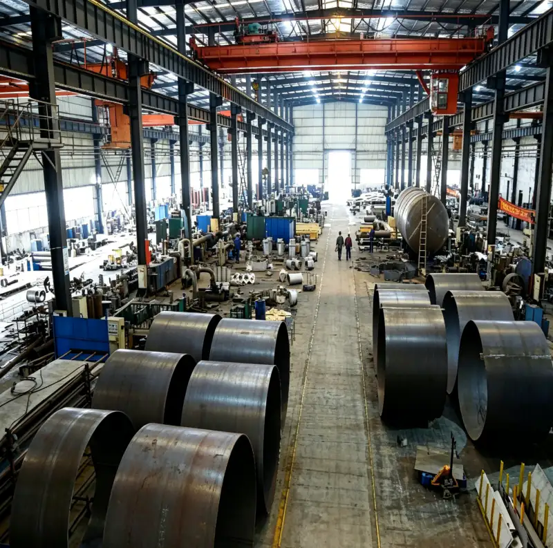
6. Validate with a pressure-versus-time test
During commissioning, record receiver pressure, compressor status, nitrogen flow and downstream demand through a representative event. The pressure curve shows whether the assumed net deficit and usable inventory were realistic. If pressure falls faster than predicted, verify demand, compressor capacity, leakage and actual receiver volume before changing setpoints. If the compressor cycles much more often than expected, review the control band and net flow. A pressure-time trace is one of the most useful acceptance records because it connects the vessel calculation with real process dynamics.
Buffer-tank sizing review
| Article | Engineering question | Verification or decision signal |
|---|---|---|
| Peak deficit | What is demand minus compressor supply during the event? | Storage is sized for the missing gas, not the entire process flow. |
| Pressure band | What high and low pressures are permitted by process and equipment? | Usable inventory is calculated within an approved operating window. |
| Cycling time | How long does the receiver take to move between setpoints? | Start-stop or load-unload frequency can be evaluated quantitatively. |
| Tank location | Is the objective source stabilization or user peak support? | Upstream and downstream receivers are sized for their own jobs. |
| Record the final basis in the RFQ, commissioning file, or maintenance record so another engineer can reproduce the decision. | ||
Project verification worksheet
Use receiver volume as a field checkpoint tied to “Define peak nitrogen demand, compressor contribution and event duration.”. Write down the measurement or inspection location, gas state, compressor load, relevant valve positions, and the document that defines acceptance. Cross-check low pressure setpoint at the same time so a local symptom is not mistaken for a whole-system problem. The concept “define demand event” is complete only when the observation leads to a clear decision: accept, correct, or escalate for supplier review. Repeat the check after any correction and keep the before-and-after values with the commissioning or maintenance record.
Before freezing the equipment choice, compare this duty with the site’s nitrogen compressor manufacturer range and confirm that the same pressure basis is being used. The cross-check here is tied to size nitrogen buffer tank peak demand compressor.
Verify “calculate usable inventory” by creating one controlled condition in which high pressure setpoint and peak demand can be interpreted together. Stabilize the system, note pressure, temperature, flow, or machine state as relevant, and use calibrated instruments or direct inspection at named locations. Carry out “Set high and low receiver pressures from process needs and approved equipment limits.” and record both expected and observed response. If a model-specific limit is required, obtain it from the selected compressor, vessel, piping, generator, or process documentation rather than inserting a generic value. The record should show why the final decision is technically defensible.
Before closing the work order, make “Use absolute pressure and temperature in the gas-inventory calculation.” traceable to evidence. For low pressure setpoint, record the reference point and unit or physical condition; for compressor capacity, record the comparison point that confirms the system is behaving coherently. Relate both observations to “select pressure band” and to the actual load or operating mode. A value without location and state is difficult to reuse later. Where the check reveals a mismatch, correct the restriction, control state, component condition, or design assumption that caused it, then repeat the same observation so the repair is proven rather than assumed.
Treat “account for compressor contribution” as a small commissioning experiment. Define the starting state, observe peak demand, change only the variable needed for the approved test, and watch the response in usable gas inventory. The action “Check real-gas or non-isothermal effects if the pressure and fill rate make them important.” should leave a record of initial condition, intervention, final condition, and any alarm or control response. This is useful when several components can create the same symptom. By changing one factor at a time and keeping the compressor inside its approved envelope, the team can separate cause from coincidence and avoid replacing hardware that was not responsible.
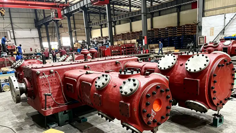
For long-term reliability, connect “Run a separate cycling-time calculation for compressor control.” with a baseline for compressor capacity. Record that baseline when the installation is clean, stable, and known to be healthy, then include receiver volume and operating load so later readings can be normalized. The review concept “check cycling frequency” should have a defined trigger for investigation even when the absolute value has not reached an alarm. A gradual departure from a reproducible baseline often gives more warning than one isolated reading. If the process configuration changes, create a new documented baseline instead of comparing unlike operating states.
During engineering review, challenge the assumption behind “verify vessel and relief design” by tracing the physical path associated with usable gas inventory and high pressure setpoint. Follow the gas, heat, force, control signal, or leakage route from source to destination and identify every component that can alter the result. Then complete “Commission the receiver with a pressure-versus-time trend during a representative event.” at the point where the decision is actually made, not at the most convenient gauge. Record any pressure drop, temperature difference, control delay, or inspection finding that explains the behavior. This path-based check prevents local measurements from being interpreted without system context.
This decision can also be cross-checked against the site’s medium capacity nitrogen compressor information before the project datasheet is released. The cross-check here is tied to size nitrogen buffer tank peak demand compressor.
Safety and verification boundary
A receiver is a pressure vessel containing stored energy. Vessel design, relief protection, supports, inspection and isolation must follow the applicable project and jurisdictional requirements. Do not raise receiver pressure setpoints to gain inventory without confirming every connected component is approved for the new pressure. Nitrogen released during relief, draining or maintenance can displace oxygen; vent paths need safe routing.
Receiver calculation sequence
- Define peak nitrogen demand, compressor contribution and event duration.
- Set high and low receiver pressures from process needs and approved equipment limits.
- Use absolute pressure and temperature in the gas-inventory calculation.
- Check real-gas or non-isothermal effects if the pressure and fill rate make them important.
- Run a separate cycling-time calculation for compressor control.
- Commission the receiver with a pressure-versus-time trend during a representative event.
Buffer-tank questions
Can I size a nitrogen receiver from compressor flow alone?
No. You need the demand profile, compressor contribution, event duration and usable pressure band. Receiver volume is a time-shifting tool, not a substitute for sustained capacity.
Does a bigger pressure band always mean a smaller tank?
A wider approved band increases usable inventory, but process minimum pressure, compressor ratio, regulator duty and vessel ratings limit how far the band can be expanded.
Should the buffer tank be before or after the booster?
Place storage where it solves the identified problem. Upstream storage stabilizes the source and suction; downstream storage supports high-pressure peaks and reduces booster cycling. Some systems need both.
Receiver-sizing rule
Size a nitrogen buffer tank from the gas inventory required between an approved high and low pressure. Subtract the gas the compressor continues to supply during the peak, check cycling separately, and place storage on the side of the compressor that addresses the real dynamic problem. Then verify the result with a pressure-time trend at site.

























