
Estimate gas power first, then separate compressor and motor losses
A useful power estimate states the gas model, inlet condition, pressure ratio and efficiency instead of treating kW as a direct function of pressure.
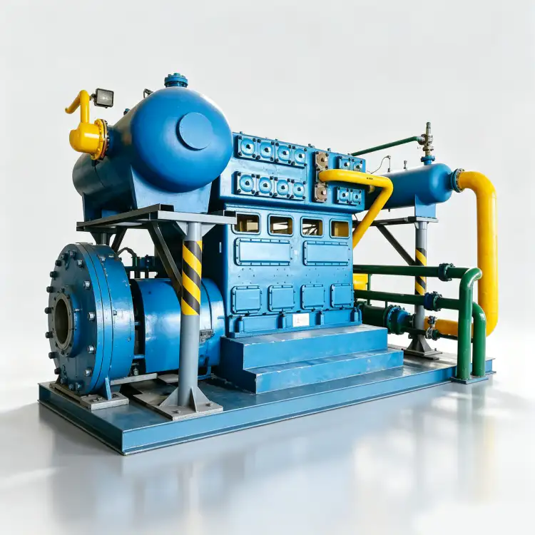
Nitrogen compressor power can be estimated from thermodynamics, but the result is only meaningful when the flow basis and efficiency assumptions are clear. A common first-pass calculation treats nitrogen as an ideal gas and estimates isentropic compression work from inlet absolute pressure, actual inlet volumetric flow, specific-heat ratio and pressure ratio. One form is W = [k/(k-1)] × P1 × Q1 × [(P2/P1)^((k-1)/k) – 1] / eta, with consistent SI units. Here eta is an assumed overall compression efficiency for the chosen level of estimate. The equation shows why high pressure ratio increases work and why interstage cooling can reduce the work of multi-stage compression. It does not replace a compressor supplier’s performance prediction. Real power depends on volumetric efficiency, mechanical losses, valve losses, cooling, leakage, motor efficiency and control mode. Use the formula to screen alternatives and test sensitivity; use vendor data for motor selection and contract guarantees.
Power-calculation variables
- isentropic power
- A thermodynamic estimate of the power needed for reversible adiabatic compression before real machine losses are added.
- specific heat ratio
- The ratio k = cp/cv for the gas at the relevant condition; use appropriate nitrogen property data for final engineering.
- inlet pressure
- Absolute compressor suction pressure used in the thermodynamic power relation.
- inlet volumetric flow
- Actual gas volume entering the compressor per unit time at the stated suction pressure and temperature.
- pressure ratio
- Absolute discharge pressure divided by absolute suction pressure.
- overall efficiency
- A clearly defined efficiency factor used to translate ideal gas power toward a realistic compressor estimate.
1. Convert flow to the actual inlet state
If the plant gives normalized flow, convert it to actual suction volume before using an equation that expects Q1 at inlet conditions. Alternatively, work from mass flow with a thermodynamic relation formulated for mass. Do not insert Nm3/h directly as if it were actual m3/h at several bar suction pressure. Record suction temperature because it affects density and the gas properties used in the calculation. For a booster, positive inlet pressure can materially change both actual volume and pressure ratio compared with an atmospheric-suction machine.
2. Use absolute pressure and consistent units
P1 and P2 must be absolute. In SI calculations, pressure in pascals multiplied by volumetric flow in cubic metres per second produces watts in the basic pressure-flow term. Convert hours to seconds if the flow begins in m3/h. Keep a units line beside the formula so a bar-to-pascal or hour-to-second error cannot hide inside a spreadsheet. If the result seems implausibly small or large, check units before changing the efficiency assumption. Dimensional discipline is the fastest quality check on a power estimate.
3. Efficiency is an assumption that must be labeled
The efficiency term can mean different things in different references—isentropic efficiency, polytropic efficiency, mechanical efficiency or a combined estimate. State exactly what you are using. Do not select a favorable efficiency from an unrelated compressor and present the resulting power as guaranteed. For early project screening, calculate a range using conservative and optimistic assumptions. When vendor proposals arrive, replace the assumed value with the supplier’s predicted shaft and motor power for the actual machine. The original calculation remains useful as an independent reasonableness check.
After confirming the field condition, review the site’s nitrogen compressor power calculation resource to match the requirement with a realistic compressor family. The cross-check here is tied to estimate power consumption of n2 compressor.

4. Multi-stage compression changes the calculation
For multiple stages, calculate work stage by stage using each stage inlet pressure and temperature rather than applying a one-stage equation across the whole ratio. Intercooling lowers the temperature entering the next stage and can reduce total work. Pressure drop through coolers and separators increases the work because the next stage must recover the lost pressure. An ideal equal-ratio, perfectly intercooled calculation is a useful lower-bound comparison, but real packages have non-ideal pressure splits and finite cooler approach temperatures. Ask for stage conditions if power is commercially important.
5. Motor input is not the same as gas compression power
The process gas receives only part of the electrical power drawn at the motor terminals. Mechanical friction, auxiliaries, motor losses, fans, pumps and controls add to the site electrical load. Conversely, a manufacturer may quote shaft power while the electrical engineer needs motor input or full-load current. Clarify the boundary of every number in the bid tab. For energy-cost estimates, use measured or vendor-predicted electrical input at the expected operating load and include auxiliary cooling power if it is supplied separately.
6. Part-load operation can dominate annual energy
A compressor sized for peak demand may spend most of the year at part load. The annual energy model should reflect how the machine controls capacity: variable speed, unload, recycle, start-stop or multiple-unit sequencing. A recycle valve can keep a compressor mechanically stable while consuming substantial power to move gas the process does not need. A variable-speed machine can reduce throughput but only within its approved speed envelope. Build a simple load-duration profile and multiply expected input power at each state by annual hours. That is more useful than comparing only full-load kW.
Power estimate audit
| Article | Engineering question | Verification or decision signal |
|---|---|---|
| Flow input | Is Q1 actual inlet volume or has mass flow been used consistently? | Normalized flow is not accidentally inserted into an inlet-volume formula. |
| Pressure ratio | Are P1 and P2 absolute? | The thermodynamic term reflects the real compression ratio. |
| Efficiency | Is the efficiency definition and source stated? | The estimate can be updated when vendor data arrive. |
| Energy model | Does annual consumption include part-load control and auxiliaries? | Ownership cost reflects the way the compressor will actually operate. |
| Record the final basis in the RFQ, commissioning file, or maintenance record so another engineer can reproduce the decision. | ||
Project verification worksheet
Close the loop on “Convert process flow to actual inlet volume or use a mass-flow formulation.” by documenting cause, response, and acceptance. Start with “define thermodynamic basis”, identify the expected behavior of isentropic power, and choose a second observation involving inlet pressure that can confirm the same conclusion independently. Perform the check without bypassing protective devices or exceeding the approved operating range. If the two signals disagree, investigate instrument accuracy, valve state, pressure loss, contamination, leakage, or control logic before deciding which component needs work. Independent confirmation is valuable when shutdown or replacement would be expensive.
For a related equipment benchmark, review the site’s nitrogen gas compressor options while checking the operating assumptions in this section. The cross-check here is tied to estimate power consumption of n2 compressor.
Turn the review item “calculate ideal power” into a recorded acceptance step. Identify where specific heat ratio is observed, the operating state at that moment, and what upstream or downstream condition could change inlet volumetric flow. Record the instrument, drawing, datasheet, or physical inspection used to establish the basis. Then perform the action “Use absolute suction and discharge pressures.” under a repeatable condition. If the result conflicts with expected behavior, hold the next design or maintenance decision until the discrepancy is explained. This gives another engineer enough context to reproduce the check without relying on memory or an undocumented assumption.
Use inlet pressure as a field checkpoint tied to “Write the specific-heat ratio and efficiency assumptions beside the equation.”. Write down the measurement or inspection location, gas state, compressor load, relevant valve positions, and the document that defines acceptance. Cross-check pressure ratio at the same time so a local symptom is not mistaken for a whole-system problem. The concept “apply efficiency” is complete only when the observation leads to a clear decision: accept, correct, or escalate for supplier review. Repeat the check after any correction and keep the before-and-after values with the commissioning or maintenance record.
Verify “consider intercooling” by creating one controlled condition in which inlet volumetric flow and overall efficiency can be interpreted together. Stabilize the system, note pressure, temperature, flow, or machine state as relevant, and use calibrated instruments or direct inspection at named locations. Carry out “Calculate stages separately when intercooling is important.” and record both expected and observed response. If a model-specific limit is required, obtain it from the selected compressor, vessel, piping, generator, or process documentation rather than inserting a generic value. The record should show why the final decision is technically defensible.
Before closing the work order, make “Distinguish gas power, shaft power, motor input and auxiliary power.” traceable to evidence. For pressure ratio, record the reference point and unit or physical condition; for isentropic power, record the comparison point that confirms the system is behaving coherently. Relate both observations to “separate shaft and electrical power” and to the actual load or operating mode. A value without location and state is difficult to reuse later. Where the check reveals a mismatch, correct the restriction, control state, component condition, or design assumption that caused it, then repeat the same observation so the repair is proven rather than assumed.
Treat “validate against vendor data” as a small commissioning experiment. Define the starting state, observe overall efficiency, change only the variable needed for the approved test, and watch the response in specific heat ratio. The action “Estimate annual energy from the expected load-duration profile.” should leave a record of initial condition, intervention, final condition, and any alarm or control response. This is useful when several components can create the same symptom. By changing one factor at a time and keeping the compressor inside its approved envelope, the team can separate cause from coincidence and avoid replacing hardware that was not responsible.
Use the site’s nitrogen compressor for air separation resource as a second check when translating this requirement into a compressor specification. The cross-check here is tied to estimate power consumption of n2 compressor.
Safety and verification boundary
Power calculations must never be used to override motor, electrical protection or mechanical ratings from the approved compressor design. The motor starter, cables and protection devices should be selected from the supplier’s electrical data and applicable electrical standards. High power also means significant heat rejection; verify the cooling system and room ventilation rather than assuming all electrical input leaves through the discharge gas.
Power calculation workflow
- Convert process flow to actual inlet volume or use a mass-flow formulation.
- Use absolute suction and discharge pressures.
- Write the specific-heat ratio and efficiency assumptions beside the equation.
- Calculate stages separately when intercooling is important.
- Distinguish gas power, shaft power, motor input and auxiliary power.
- Estimate annual energy from the expected load-duration profile.
Power-estimation questions
Can I estimate kW from Nm3/h multiplied by pressure?
That shortcut ignores the logarithmic or ratio-dependent nature of gas compression, inlet state and efficiency. Use a thermodynamic compression relation and a clearly defined flow basis.
What efficiency should I assume?
Use a range suitable for preliminary screening and label it as an assumption. Replace it with supplier performance for the selected compressor before final motor or lifecycle-cost decisions.
Why can a higher suction pressure change power in two directions?
It reduces pressure ratio for a fixed discharge pressure but increases gas density and potential mass throughput. The net driver load must be checked at the actual capacity and inlet condition.
Power estimate rule
Estimate N2 compressor power from a transparent thermodynamic basis: actual inlet gas condition, absolute pressure ratio, nitrogen properties and a stated efficiency. Then distinguish ideal gas power from shaft, motor and auxiliary consumption. Use the estimate for screening and sanity checks, while relying on supplier performance for final electrical design.

























