
Booster inlet pressure changes density and pressure ratio at the same time
Higher suction pressure can increase nitrogen mass throughput while reducing compression ratio, so driver load must be checked rather than assumed.
A nitrogen booster is unusual compared with an atmospheric-suction compressor because its inlet pressure can vary over a meaningful positive range. When inlet pressure rises at roughly constant temperature, nitrogen density increases. If compressor speed and volumetric efficiency remain similar, each swept cubic metre contains more gas and mass throughput can increase. At the same time, a fixed discharge pressure produces a lower compression ratio, which tends to reduce specific compression work per unit mass. These two effects move in different directions for total power: more mass may be compressed, but each unit of mass may require less pressure-ratio work. The actual driver demand depends on the compressor design and control mode. When inlet pressure falls, capacity may drop and ratio rises, often increasing discharge temperature. For this reason, booster suppliers need both minimum and maximum suction pressure. The low-inlet case may control capacity and temperature, while the high-inlet case may control motor power, rod load or maximum allowable cylinder forces.
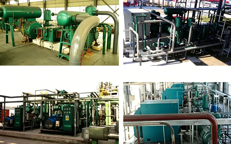
Variables that move with booster inlet pressure
- booster inlet pressure
- Absolute pressure at the booster suction flange over the full upstream operating range.
- gas density
- Nitrogen mass per unit inlet volume, which increases with absolute pressure at constant temperature.
- pressure ratio
- Fixed discharge absolute pressure divided by changing inlet absolute pressure.
- mass throughput
- Nitrogen mass delivered per unit time, affected by inlet density, speed and volumetric efficiency.
- valve loading
- Flow and pressure forces acting on suction and discharge valves as mass throughput and pressure ratio change.
- driver power
- Mechanical or electrical power required at the selected operating point, verified from compressor performance data.
1. Compare inlet states using absolute pressure and temperature
Start with the actual booster suction pressure and temperature. For a first density comparison, rho is proportional to P/T. If inlet absolute pressure rises by a significant amount while temperature remains similar, density rises accordingly. That does not guarantee the same percentage increase in delivered normalized flow because volumetric efficiency, valve losses, control position and speed may also change. It does show why a booster can move much more nitrogen when connected to a stronger upstream source. Build the duty table with minimum, normal and maximum inlet pressure rather than one nominal value.
2. Low inlet pressure usually creates the highest compression ratio
With a fixed discharge target, reducing P1_abs increases P2_abs/P1_abs. Higher ratio can raise discharge temperature and reduce volumetric efficiency. A booster that is comfortable at normal source pressure may lose capacity or approach a thermal limit as the upstream receiver empties. Define a low-suction shutdown or unload condition that protects both the booster and the nitrogen source. Do not simply allow the compressor to keep pulling until the upstream generator or header collapses; the resulting unstable operating point can create repeated trips and poor purity control.
3. High inlet pressure can become the driver-load case
At high inlet pressure, ratio is lower but the cylinder fills with denser gas. Mass throughput can increase, and so can forces and driver demand. The exact relationship is not linear because the compressor’s valves, clearance and control strategy respond to the new condition. Ask the supplier to calculate power and mechanical loading at the maximum approved inlet pressure. This is especially important if the process normally operates at lower pressure but can occasionally receive a stronger supply from a full receiver or alternate nitrogen source. A motor selected only from the low-inlet case can be misleading.
For an application-specific cross-check, use the site’s nitrogen booster compressor page alongside the measured duty data discussed above. The cross-check here is tied to inlet pressure changes nitrogen booster flow power.
4. Upstream generator behavior sets the practical pressure range
If the booster is fed by PSA or membrane generation, suction pressure is not an independent variable. High booster demand can drain the product receiver and change the generator operating point. The usable minimum pressure should protect generator stability and product purity as well as compressor performance. A low-pressure receiver can smooth the supply, but its pressure band and refill rate need to be coordinated with the booster. Trend generator outlet, receiver pressure and booster suction together during a peak event. If the pressure falls steadily, the source and booster capacities are not in balance.
5. Controls should respond to both suction and discharge conditions
A booster control loop focused only on discharge pressure may command more capacity while suction is collapsing. Include a minimum suction permissive, and where appropriate use receiver pressure, generator status or product purity in the sequence. Variable speed can reduce demand if the compressor is approved for the required speed range. Other packages may unload or recycle. The chosen method should avoid rapid hunting between low-suction and high-discharge limits. Simulate these transitions before commissioning so the plant knows which signal has priority when conditions conflict.
6. Use a pressure-sweep performance table for procurement and testing
Ask the supplier for several operating points at the same discharge pressure: minimum, normal and maximum suction pressure, each with capacity, power and predicted stage temperatures. This table exposes which limit controls each end of the range. During site testing, it may not be practical to reproduce every point, but trend data can show how flow and load change as the upstream receiver cycles. If the measured relationship differs sharply from the predicted trend, verify pressure and flow reference conditions before assuming a compressor defect.
Inlet-pressure sensitivity table
| Article | Engineering question | Verification or decision signal |
|---|---|---|
| Minimum inlet | What happens to capacity and discharge temperature at the weakest source pressure? | Low-suction protection is set above an unstable or excessive-ratio condition. |
| Maximum inlet | What happens to mass flow, driver power and mechanical loading? | The motor and compressor are safe at the strongest source pressure. |
| Source balance | Can the nitrogen generator or header sustain booster draw? | Receiver pressure recovers instead of trending downward through the demand cycle. |
| Control logic | How does the booster respond when suction and discharge limits compete? | The machine unloads or slows without destabilizing the source. |
| Record the final basis in the RFQ, commissioning file, or maintenance record so another engineer can reproduce the decision. | ||
Project verification worksheet
Verify “compare inlet states” at the boundary where its consequence appears. Observe booster inlet pressure at its source and pressure ratio at the receiving side, then complete “List minimum, normal and maximum absolute booster inlet pressure.” while relevant flow and pressure are stable. Record enough context to distinguish normal process variation from equipment deterioration. When exact acceptance limits depend on the selected model, use current manufacturer documentation or the approved project specification. Do not transfer a value from another compressor merely because the service sounds similar. A boundary-to-boundary record makes later troubleshooting much faster.
After confirming the field condition, review the site’s nitrogen gas compressor resource to match the requirement with a realistic compressor family. The cross-check here is tied to inlet pressure changes nitrogen booster flow power.
Close the loop on “Pair inlet pressure with expected suction temperature to compare density.” by documenting cause, response, and acceptance. Start with “calculate pressure ratio shift”, identify the expected behavior of gas density, and choose a second observation involving mass throughput that can confirm the same conclusion independently. Perform the check without bypassing protective devices or exceeding the approved operating range. If the two signals disagree, investigate instrument accuracy, valve state, pressure loss, contamination, leakage, or control logic before deciding which component needs work. Independent confirmation is valuable when shutdown or replacement would be expensive.
Turn the review item “estimate mass-flow effect” into a recorded acceptance step. Identify where pressure ratio is observed, the operating state at that moment, and what upstream or downstream condition could change valve loading. Record the instrument, drawing, datasheet, or physical inspection used to establish the basis. Then perform the action “Calculate pressure ratio at the low-inlet case.” under a repeatable condition. If the result conflicts with expected behavior, hold the next design or maintenance decision until the discrepancy is explained. This gives another engineer enough context to reproduce the check without relying on memory or an undocumented assumption.
Use mass throughput as a field checkpoint tied to “Require supplier power and mechanical checks at the high-inlet case.”. Write down the measurement or inspection location, gas state, compressor load, relevant valve positions, and the document that defines acceptance. Cross-check driver power at the same time so a local symptom is not mistaken for a whole-system problem. The concept “check compressor map or vendor curve” is complete only when the observation leads to a clear decision: accept, correct, or escalate for supplier review. Repeat the check after any correction and keep the before-and-after values with the commissioning or maintenance record.
Verify “protect upstream generator” by creating one controlled condition in which valve loading and booster inlet pressure can be interpreted together. Stabilize the system, note pressure, temperature, flow, or machine state as relevant, and use calibrated instruments or direct inspection at named locations. Carry out “Coordinate low-suction logic with upstream receiver and generator behavior.” and record both expected and observed response. If a model-specific limit is required, obtain it from the selected compressor, vessel, piping, generator, or process documentation rather than inserting a generic value. The record should show why the final decision is technically defensible.
Before closing the work order, make “Collect flow, power and temperature data across a natural receiver-pressure cycle.” traceable to evidence. For driver power, record the reference point and unit or physical condition; for gas density, record the comparison point that confirms the system is behaving coherently. Relate both observations to “set control limits” and to the actual load or operating mode. A value without location and state is difficult to reuse later. Where the check reveals a mismatch, correct the restriction, control state, component condition, or design assumption that caused it, then repeat the same observation so the repair is proven rather than assumed.
For a related equipment benchmark, review the site’s reciprocating nitrogen compressor options while checking the operating assumptions in this section. The cross-check here is tied to inlet pressure changes nitrogen booster flow power.
Safety and verification boundary
A pressurized booster suction line can feed energy back into the machine after shutdown, so isolation must cover the upstream source as well as the discharge receiver. Non-return valves are not a substitute for positive maintenance isolation. Nitrogen vents and relief discharges should terminate safely. Maximum suction pressure is a mechanical design input; never raise it in the field without written approval for the specific compressor package.
Booster pressure-sweep checklist
- List minimum, normal and maximum absolute booster inlet pressure.
- Pair inlet pressure with expected suction temperature to compare density.
- Calculate pressure ratio at the low-inlet case.
- Require supplier power and mechanical checks at the high-inlet case.
- Coordinate low-suction logic with upstream receiver and generator behavior.
- Collect flow, power and temperature data across a natural receiver-pressure cycle.
Inlet-pressure questions
Does higher inlet pressure always reduce compressor power?
No. It reduces pressure ratio for a fixed discharge pressure, but higher inlet density can increase mass throughput. Total driver power depends on both effects and the compressor design.
Which inlet pressure should be used for motor sizing?
Ask the manufacturer to identify the maximum-power case across the full approved suction range. It may not be the same condition that produces the highest compression ratio.
Why does my booster flow fall as the receiver empties?
Lower inlet pressure reduces gas density and can reduce volumetric efficiency as compression ratio rises. The compressor may also encounter a low-suction control limit before the receiver reaches its minimum pressure.
How to interpret inlet pressure
Inlet pressure changes a nitrogen booster in two simultaneous ways: it changes how much gas fits into each inlet volume and it changes the pressure ratio to the final header. Check low inlet for capacity and temperature, high inlet for mass throughput and driver loading, and design controls around the upstream source so the booster does not create its own suction problem.

























