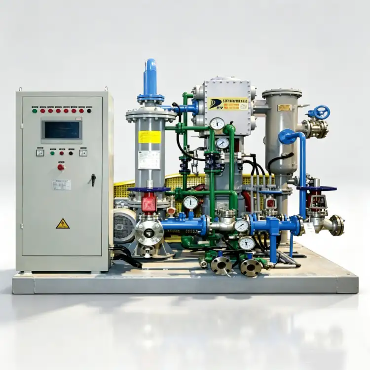
Systematic Diagnosis for Nitrogen Compressor Failures
Nitrogen compressor failures do not occur randomly. Every symptom traces to a specific root cause that, once identified, can be corrected with targeted action. The difference between a maintenance technician who replaces three components to fix one problem and a diagnostic engineer who identifies the true fault in the first attempt is systematic troubleshooting methodology. This guide presents the most common nitrogen compressor problems and their solutions, organized by symptom, diagnostic logic, and corrective procedure.
The troubleshooting frameworks here apply to reciprocating, diaphragm, and screw nitrogen compressors across industrial applications from chemical processing to pharmaceutical manufacturing. Each section provides observable symptoms, probable cause hierarchies, verification tests, and step-by-step corrective actions.
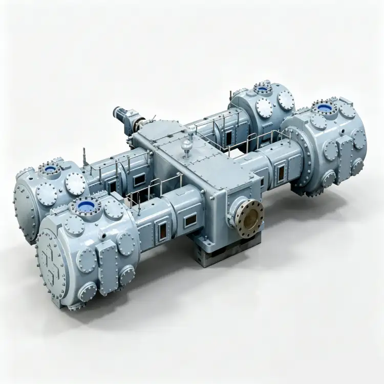
Problem: Compressor Fails to Start or Start Then Trips
A compressor that refuses to start or trips immediately after starting represents a complete operational halt. The diagnostic challenge is distinguishing between electrical, mechanical, and control system causes without inducing further damage through repeated restart attempts.
Electrical Causes
Symptoms: Motor hums but does not rotate; motor starter trips on overload; control panel displays undervoltage or phase loss alarm.
Diagnostic Procedure:
- Verify supply voltage at motor terminals with a calibrated multimeter. Compare against motor nameplate ratings (typically ±10% tolerance). Three-phase voltage imbalance should not exceed 2%.
- Check phase sequence with a phase rotation meter. Incorrect phase sequence causes motor to rotate in reverse or fail to start.
- Measure insulation resistance (megger test) between motor windings and ground. Values below 1 MΩ indicate winding degradation or moisture ingress.
- Inspect motor starter contacts for pitting, welding, or contamination. Measure contact resistance; values above 50 mΩ indicate contact deterioration.
- Verify overload relay settings match motor full-load current. Incorrect settings cause nuisance tripping or inadequate protection.
Corrective Actions: Correct voltage supply issues with power conditioning equipment or utility coordination. Replace damaged motor windings or rewind the motor. Clean or replace starter contacts. Adjust overload relay settings to manufacturer specifications. For phase loss conditions, install phase monitoring relays that prevent starting with missing phases.
Mechanical Causes
Symptoms: Motor attempts to start but stalls; high starting current followed by trip; mechanical binding noise during start attempt.
Diagnostic Procedure:
- With power locked out, attempt to rotate the compressor flywheel by hand. Binding or seizure indicates mechanical obstruction.
- Remove cylinder heads and inspect for liquid accumulation (hydraulic lock from condensate or oil pooling in cylinders).
- Check bearing condition by measuring radial play in crankshaft and connecting rod bearings. Excessive play indicates seizure risk.
- Inspect piston-to-cylinder clearance with feeler gauges. Tight clearances from thermal expansion or foreign object ingestion cause binding.
- Verify unloader operation. A stuck-closed unloader forces the compressor to start against full discharge pressure, exceeding motor torque capability.
Corrective Actions: Drain all liquid from cylinders, receivers, and piping before restart. Replace seized bearings and inspect crankshaft for scoring. Remove foreign objects and inspect cylinder walls for damage. Repair or replace malfunctioning unloaders. For screw compressors, verify that the inlet valve opens fully during startup sequence.
Control System Causes
Symptoms: Control panel displays fault codes; compressor does not respond to start command; safety interlocks prevent starting.
Diagnostic Procedure:
- Read and record all fault codes from the control panel. Cross-reference against manufacturer fault code documentation.
- Verify that all safety interlocks are satisfied: low oil pressure switch (lubricated compressors), high temperature switch, emergency stop button, pressure relief valve status.
- Test control circuit continuity with a multimeter. Open circuits in safety chains prevent starting even when all conditions appear normal.
- Inspect programmable logic controller (PLC) or relay logic for failed components, loose connections, or program corruption.
Corrective Actions: Reset fault codes after addressing root causes. Replace failed sensors and switches. Repair control circuit wiring. Update or reload PLC programs if corruption is suspected. Document all control system modifications for future reference.
For facilities operating industrial nitrogen compressor systems, maintaining a startup troubleshooting checklist at the compressor station eliminates diagnostic guesswork and standardizes response procedures across shift personnel.
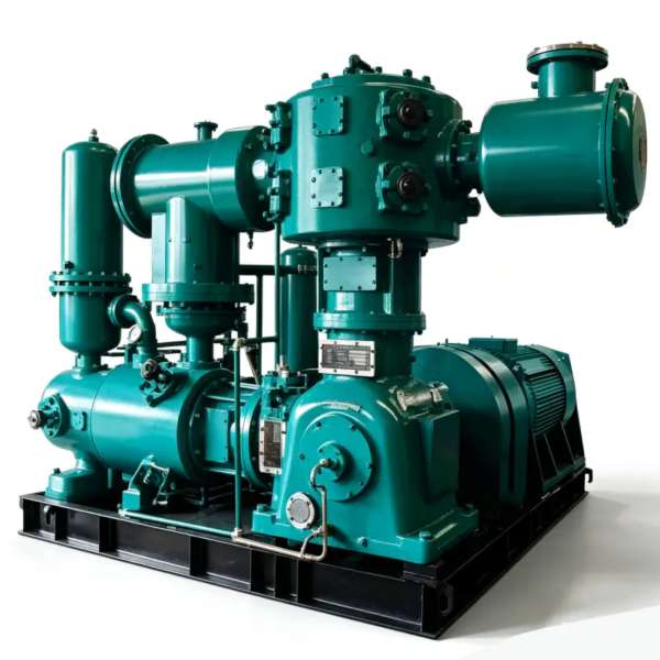
Problem: Insufficient Discharge Pressure or Flow Capacity
Reduced capacity is the most economically damaging compressor fault because it directly impacts production throughput. A 10% capacity reduction in a continuous process may force production slowdown or batch extension, with costs far exceeding the compressor repair expense.
Primary Cause: Valve Degradation — Suction and discharge valves are the most common source of capacity loss in reciprocating compressors. Leaking valves allow gas to recirculate rather than progressing through the compression cycle. The diagnostic signature is distinctive: discharge temperature increases while capacity decreases.
Verification: Measure interstage pressures (for multi-stage compressors) or compare actual discharge pressure against design curves at measured flow. A leaking discharge valve shows elevated suction pressure and reduced discharge pressure. A leaking suction valve shows reduced suction pressure and elevated discharge temperature. Use an infrared thermometer to identify hot valves—valves with internal leakage run 20-50°C hotter than properly sealing valves.
Correction: Replace valve assemblies. Do not attempt to repair individual valve plates or springs—replace the complete assembly to ensure consistent performance. Inspect valve seats for pitting or erosion; damaged seats require cylinder head machining or replacement. After valve replacement, verify capacity recovery through flow measurement and compare against baseline performance data.
Secondary Cause: Piston Ring Wear — Worn piston rings allow blow-by from the high-pressure side to the low-pressure side, reducing volumetric efficiency. Oil-lubricated rings typically last 8,000-16,000 hours; oil-free rings last 4,000-8,000 hours.
Verification: Measure blow-by at the crankcase vent. Excessive flow indicates ring leakage. For oil-lubricated compressors, monitor oil consumption—worn rings increase oil migration into the gas stream. Perform a capacity test: measure actual flow at rated discharge pressure and compare against manufacturer performance curves. A 5-10% capacity drop correlates with moderate ring wear; 15-20% drop indicates severe wear requiring immediate replacement.
Correction: Replace piston rings during scheduled outage. Inspect cylinder walls for scoring, ovality, or taper. If wall damage exceeds manufacturer limits, rebore the cylinder and install oversize pistons and rings. For oil-free compressors, inspect self-lubricating ring material for cracking, chipping, or excessive wear. Replace distance piece seals to prevent oil vapor migration (in oil-free designs with separate crankcase).
Tertiary Cause: Drive System Issues — Reduced motor speed, slipping belts, or coupling misalignment decrease compressor output proportionally.
Verification: Measure actual compressor speed with a tachometer and compare against design RPM. Check belt tension with a tension gauge; loose belts slip under load. Inspect coupling alignment with dial indicators; misalignment reduces power transmission efficiency. For VSD-driven compressors, verify that the drive is commanding full speed and that the motor is responding correctly.
Correction: Adjust belt tension to manufacturer specification (typically 10-15 mm deflection at mid-span under moderate finger pressure). Realign coupling within 0.05 mm parallel and angular tolerance. For VSD issues, verify parameter settings, encoder feedback, and power module health. Replace worn belts as a set—mixing old and new belts causes uneven loading.
Screw Compressor Specific Causes: Capacity loss in screw compressors typically results from airend wear, inlet valve malfunction, or control system issues. Airend wear increases internal leakage paths between rotors and housing, reducing volumetric efficiency. Inlet valves that fail to open fully restrict suction flow. Capacity control systems (slide valves or variable speed drives) that malfunction operate at reduced output unnecessarily.
Verification: Measure airend discharge temperature—elevated temperatures indicate increased internal leakage. Inspect inlet valve position indicator during operation. Test capacity control system response to setpoint changes.
Correction: Airend overhaul or replacement addresses wear. Inlet valve repair or replacement restores full flow. Control system recalibration or PLC program updates resolve capacity control malfunctions.
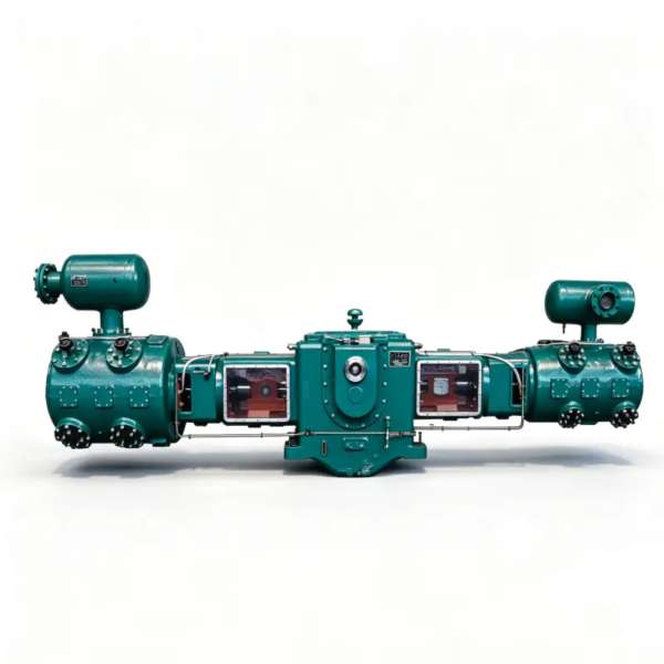
Problem: Excessive Discharge Temperature
Elevated discharge temperature is both a symptom and a cause of compressor damage. High temperatures degrade lubricating oil, accelerate seal aging, reduce material strength, and can trigger automatic shutdowns. Addressing the root cause promptly prevents cascading failures.
Cause 1: Cooling System Degradation — The most common source of high discharge temperature is inadequate heat rejection.
Diagnostic Procedure:
- Measure cooling water inlet temperature and flow rate. Inlet temperature should not exceed 30°C; flow rate should match design specification (±10%).
- Measure cooling water outlet temperature. A temperature rise of less than 5°C indicates insufficient heat transfer (fouled tubes, low flow) or insufficient load.
- Inspect heat exchanger tubes for scale, fouling, or blockage. A 1 mm scale layer reduces heat transfer by 20-30%.
- For air-cooled units, inspect cooling fins for dust accumulation and verify fan operation and motor current draw.
- Check thermostat and temperature control valve operation. A stuck thermostat may prevent full cooling flow.
Correction: Clean heat exchanger tubes chemically or mechanically. Adjust cooling water flow to design rate. Replace malfunctioning thermostats and control valves. Clean air-cooled fins and verify adequate airflow clearance. In extreme cases, upgrade cooling capacity or add supplementary cooling.
Cause 2: Valve Leakage — Leaking discharge valves allow hot compressed gas to flow back into the cylinder during the suction stroke, mixing with incoming gas and elevating the average cylinder temperature.
Diagnostic Procedure: Measure valve temperatures with an infrared thermometer. Leaking valves run 20-50°C hotter than properly sealing valves. Measure interstage pressures; leaking valves cause abnormal pressure ratios between stages.
Correction: Replace valve assemblies. Verify valve seat integrity; damaged seats require machining or cylinder head replacement.
Cause 3: Excessive Pressure Ratio — Operating at pressure ratios above design increases adiabatic compression temperature. Each stage of a multi-stage compressor has a design pressure ratio (typically 3:1 to 4:1). Exceeding this ratio causes excessive discharge temperature.
Diagnostic Procedure: Calculate actual pressure ratio (discharge pressure / suction pressure) for each stage. Compare against manufacturer design limits. Verify that interstage pressures match design values; abnormal interstage pressures indicate valve or ring problems affecting stage balance.
Correction: Reduce discharge pressure setpoint if operation exceeds design limits. Address valve or ring problems causing abnormal interstage pressures. For applications requiring higher pressure than the compressor design, add a booster stage or replace with higher-pressure-rated equipment.
Cause 4: Low Suction Pressure — Reduced suction pressure (from upstream restrictions, filter clogging, or supply problems) increases the pressure ratio for a given discharge pressure, elevating discharge temperature.
Diagnostic Procedure: Measure suction pressure at the compressor inlet. Compare against design minimum. Inspect upstream filters, regulators, and piping for restrictions. Verify nitrogen supply system (PSA generator, vaporizer, pipeline) is delivering design pressure and flow.
Correction: Clean or replace clogged filters. Remove upstream restrictions. Repair nitrogen supply system deficiencies. Adjust process controls to maintain adequate suction pressure.
Cause 5: Lubrication Problems — Inadequate or degraded lubrication increases friction heat in bearings and cylinder walls, contributing to elevated temperatures.
Diagnostic Procedure: Verify oil level at proper mark. Check oil filter differential pressure; clogged filters restrict oil flow. Sample oil for viscosity, TAN, and contamination. Verify oil pump operation and pressure (for force-lubricated systems).
Correction: Add oil to proper level. Replace clogged oil filters. Change degraded oil. Repair or replace oil pump. For oil-free compressors, verify that self-lubricating components are not overheating due to excessive friction.
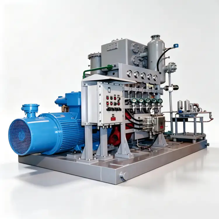
Problem: Excessive Vibration and Noise
Vibration and noise are early warning indicators of mechanical distress. Left unaddressed, they progress to component failure, secondary damage, and catastrophic shutdown. The diagnostic challenge is distinguishing between normal operational vibration and abnormal mechanical defect signatures.
Normal vs. Abnormal Vibration: All reciprocating compressors generate pulsating forces that create vibration. Normal vibration levels depend on compressor size, speed, and mounting. As a general guideline, bearing housing vibration velocity should not exceed 4.5 mm/s RMS for general industrial compressors or 2.8 mm/s RMS for critical service compressors. Exceeding these values indicates developing mechanical problems.
Cause 1: Mechanical Unbalance — Unbalance in rotating components (flywheel, motor rotor, coupling) creates vibration at 1× rotational frequency.
Diagnostic Procedure: Conduct vibration spectrum analysis. Unbalance produces a dominant peak at 1× running speed (e.g., 25 Hz for a 1,500 RPM compressor). Amplitude increases with speed squared. Phase analysis shows consistent phase angle across measurement points.
Correction: Balance rotating components in situ using portable balancing equipment or remove for shop balancing. Check for foreign material buildup on flywheels or fan blades. Verify that all balancing weights remain secure.
Cause 2: Misalignment — Shaft misalignment between motor and compressor creates vibration at 2× rotational frequency with significant axial vibration component.
Diagnostic Procedure: Vibration spectrum shows dominant 2× peak with axial vibration amplitude exceeding 50% of radial amplitude. Phase analysis reveals 180° phase difference across the coupling. Thermal growth during operation may cause misalignment that is not present during cold alignment checks.
Correction: Realign coupling using dial indicators or laser alignment tools. Account for thermal growth by measuring alignment at operating temperature and adjusting cold alignment offsets accordingly. Check for loose foundation bolts, deteriorated grout, or piping strain that shifts alignment during operation.
Cause 3: Bearing Defects — Rolling element bearing defects produce characteristic vibration frequencies based on bearing geometry and defect location.
Diagnostic Procedure: Vibration spectrum analysis identifies peaks at bearing defect frequencies: BPFI (inner race), BPFO (outer race), BSF (ball), and FTF (cage). Amplitude increases as defect severity progresses. Shock pulse measurement detects early-stage bearing defects before they appear in vibration spectra.
Correction: Replace bearings at the first indication of defect. Do not attempt to run bearings to failure—seizure destroys the shaft, housing, and often adjacent components. Verify that replacement bearings match the original specification including clearance, material, and lubrication requirements.
Cause 4: Pulsation and Acoustic Resonance — Reciprocating compressors generate pressure pulsation at multiples of running speed. If pulsation frequencies match piping acoustic natural frequencies, resonance amplifies vibration and noise dramatically.
Diagnostic Procedure: Measure vibration at multiple points along discharge piping. Resonance shows high vibration at specific locations with node points (low vibration) between them. Pulsation frequency analysis identifies coincidence between compressor-generated frequencies and piping natural frequencies.
Correction: Install pulsation dampeners or acoustic filters at the compressor discharge. Modify piping length or add supports to shift natural frequencies away from excitation frequencies. Add orifice plates to dampen pulsation energy. In severe cases, redesign piping layout with professional pulsation analysis.
Cause 5: Loose or Damaged Components — Loose mounting bolts, broken supports, cracked frames, or worn coupling elements create vibration with broadband frequency content rather than discrete peaks.
Diagnostic Procedure: Visual inspection identifies loose bolts, cracked welds, or broken supports. Impact testing (tapping with a hammer and measuring response) identifies loose connections. Vibration spectrum shows multiple frequency peaks without clear pattern.
Correction: Torque all mounting bolts to specification. Replace broken supports and repair cracked frames. Replace worn coupling elements. Verify that vibration isolation mounts are intact and properly loaded.
برای سازمانهایی که به دنبال vibration analysis support for nitrogen compressor diagnostics, establishing a baseline vibration survey during commissioning enables effective trending and early fault detection.
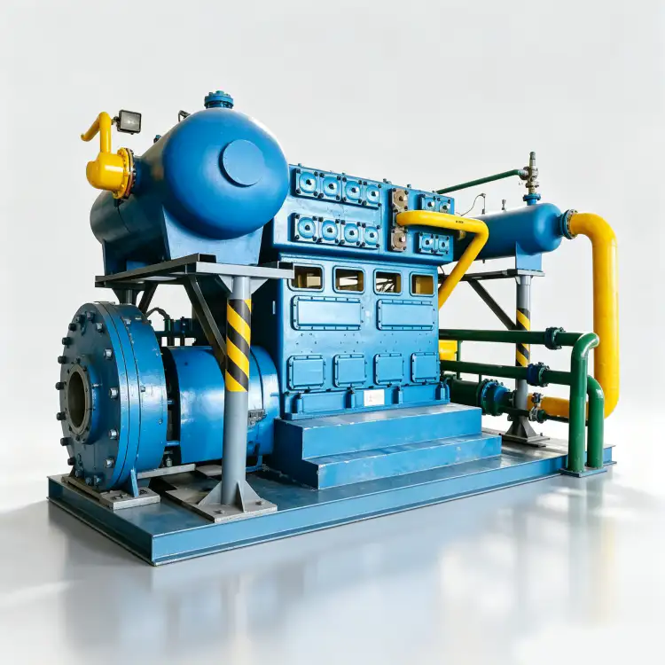
Problem: Oil Carryover and Contamination
Oil carryover from lubricated compressors contaminates downstream nitrogen, damages process equipment, and violates purity specifications. In food, pharmaceutical, and electronics applications, oil contamination causes product rejection, regulatory violations, and customer claims.
Cause 1: Worn Piston Rings (Reciprocating) — Piston rings that no longer seal effectively allow crankcase oil to migrate past the piston into the compression chamber and then into the discharge stream.
Diagnostic Procedure: Monitor oil consumption rate. Normal oil consumption is 0.5-2.0 grams per hour per cylinder; excessive consumption indicates ring leakage. Measure oil content in discharge nitrogen using oil mist detectors or laboratory analysis. Inspect rings during scheduled maintenance for wear, breakage, or loss of tension.
Correction: Replace piston rings. Inspect cylinder walls for scoring or glazing that prevents ring sealing. Hone or rebore cylinders if wall condition is inadequate. Verify that ring end gaps and side clearances meet manufacturer specifications. For oil-free compressors, inspect self-lubricating ring material for degradation that increases particulate generation.
Cause 2: Failed Oil Separator (Screw Compressors) — Oil-injected screw compressors rely on coalescing separators to remove oil from the compressed gas. Separator element failure allows massive oil carryover.
Diagnostic Procedure: Monitor separator differential pressure. A sudden drop in differential pressure indicates element rupture or bypass. Check oil reservoir level—rapid depletion indicates carryover. Measure oil content in discharge gas. Inspect separator element for damage, saturation, or collapse.
Correction: Replace separator element immediately. Investigate root cause: element oversaturated from extended service, oil degradation causing foaming, or excessive oil level in reservoir. Verify separator housing integrity and drain trap operation. After replacement, monitor oil content for 24 hours to confirm correction.
Cause 3: Excessive Oil Level or Foaming — Overfilled crankcases or oil reservoirs cause oil to be drawn into the gas stream. Oil foaming (from degradation, water contamination, or incorrect viscosity) increases oil volume and carryover potential.
Diagnostic Procedure: Verify oil level at proper mark—overfilling is a common operator error. Inspect oil for foam, emulsion, or discoloration indicating degradation or water contamination. Test oil viscosity and compare against specification. Check for water contamination through crackle test or laboratory analysis.
Correction: Drain excess oil to proper level. Change degraded or contaminated oil. Identify and eliminate water ingress source (cooling system leakage, atmospheric condensation, improper storage). Add antifoam agent if specified by manufacturer. Verify that oil fill procedures are standardized and training is current.
Cause 4: High Discharge Temperature — Elevated discharge temperatures reduce oil viscosity and increase vapor pressure, promoting oil vaporization and carryover.
Diagnostic Procedure: Measure discharge temperature and compare against design maximum (typically 160-180°C for mineral oils, 200°C for synthetics). If temperature exceeds limits, address root cause as described in the excessive discharge temperature section.
Correction: Reduce discharge temperature through cooling system improvement, valve replacement, or pressure ratio reduction. Consider upgrading to synthetic oil with higher thermal stability if operating temperatures consistently approach mineral oil limits.
Cause 5: Scraper Ring Failure — Oil scraper rings (wiper rings) on the piston rod prevent oil migration from the crankcase into the distance piece and compression chamber. Failed scraper rings allow oil to reach the process gas.
Diagnostic Procedure: Inspect scraper rings during maintenance for wear, breakage, or loss of tension. Check for oil accumulation in the distance piece vent. Measure oil content in distance piece vent gas.
Correction: Replace scraper rings. Verify that ring material is compatible with operating temperature and oil type. Ensure proper installation orientation (scraper edges facing crankcase). Check piston rod surface condition—scoring or corrosion accelerates scraper ring wear.
For applications where oil contamination is unacceptable, the definitive solution is oil-free compressor technology. Ever-Power’s oil-free ZW and DW series, manufactured with full ISO 8573-1 Class 0 certification, eliminate oil carryover at the source. For buyers evaluating oil-free nitrogen compressor solutions, understanding carryover mechanisms validates the oil-free investment decision.
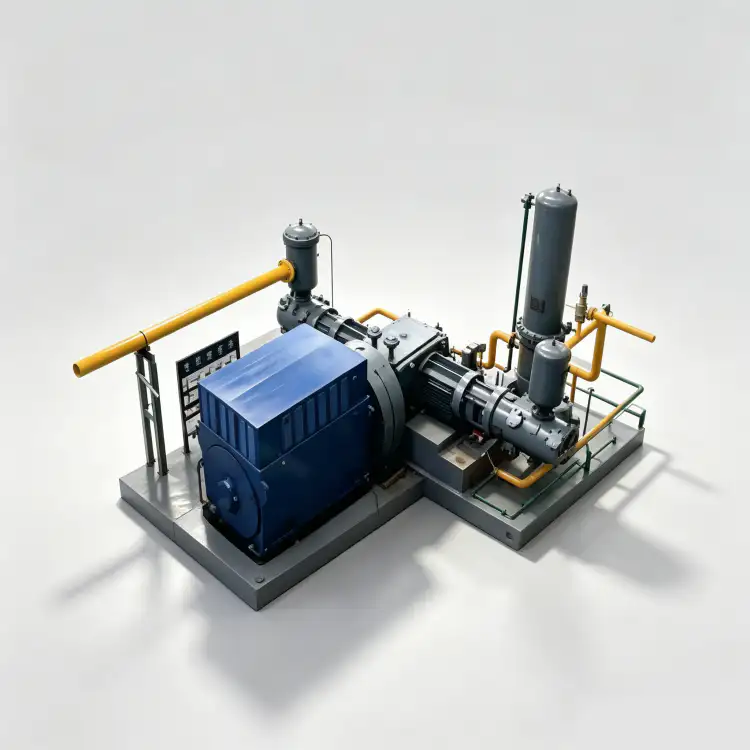
Problem: Diaphragm Compressor Specific Failures
Diaphragm compressors operate on fundamentally different principles than reciprocating or screw compressors, and their failure modes are equally distinct. Understanding these unique failure mechanisms is essential for effective troubleshooting.
Failure 1: Diaphragm Rupture — The diaphragm is the critical barrier between hydraulic oil and process gas. Fatigue, overpressure, or material defects cause rupture, resulting in immediate gas contamination and compressor shutdown.
Symptoms: Sudden capacity loss; gas contamination of hydraulic oil (visible bubbles in oil sight glass); pressure fluctuations; automatic shutdown on gas-side pressure loss or oil-side pressure anomaly.
Diagnostic Procedure: Inspect hydraulic oil for gas bubbles or discoloration. Measure gas content in hydraulic oil using dissolved gas analysis. Perform pressure hold test on gas side—rapid pressure decay indicates diaphragm breach. Borescope inspection of the diaphragm cavity reveals rupture location and pattern.
Correction: Replace diaphragm assembly. Inspect hydraulic system for gas contamination—drain and flush oil if contaminated. Investigate root cause: overpressure from process upset, excessive pressure differential, material fatigue from extended service, or manufacturing defect. Adjust operating parameters to prevent recurrence. Verify that rupture detection system (pressure monitoring, oil level monitoring) functioned correctly and is calibrated.
Failure 2: Hydraulic System Malfunction — The hydraulic drive system that flexes the diaphragm must deliver precise, controlled oil displacement. Pump failure, valve malfunction, or oil contamination disrupts this control.
Symptoms: Erratic capacity; incomplete diaphragm displacement; unusual hydraulic noise; elevated hydraulic oil temperature.
Diagnostic Procedure: Measure hydraulic pump output pressure and flow. Verify check valve operation (leaking check valves allow backflow during the return stroke). Inspect hydraulic oil for contamination (particulates, water, gas). Test hydraulic relief valve setpoint and freedom of operation.
Correction: Repair or replace hydraulic pump. Replace leaking check valves. Change contaminated hydraulic oil and identify contamination source. Adjust or replace relief valve. Verify hydraulic system filtration is adequate and maintained.
Failure 3: Head Gasket Leakage — The gas head gasket seals the compression chamber. Leakage reduces capacity and may allow gas escape to atmosphere.
Symptoms: Capacity reduction without diaphragm rupture indicators; gas odor near compressor head; bubble formation when leak detection fluid applied to gasket joint.
Diagnostic Procedure: Apply leak detection fluid (soapy water or commercial leak detector) to head gasket joints. Pressurize gas side and monitor for pressure decay. Inspect gasket condition during maintenance for compression set, cracking, or material degradation.
Correction: Replace head gasket. Verify that gasket material is compatible with nitrogen temperature and pressure. Torque head bolts to manufacturer specification in proper sequence to ensure even gasket compression. Inspect head and body sealing surfaces for damage or corrosion that prevents proper sealing.
Diaphragm compressor troubleshooting requires specialized knowledge of hydraulic systems, gas sealing, and fatigue mechanics. Maintenance personnel should receive manufacturer-specific training before attempting independent repairs. The high purity requirements of diaphragm compressor applications make contamination prevention paramount during any maintenance activity.

Problem: Control System and Instrumentation Malfunctions
Modern nitrogen compressors rely on sophisticated control systems for capacity modulation, safety protection, and operational optimization. When these systems malfunction, the compressor may operate inefficiently, shut down unnecessarily, or fail to protect against dangerous conditions.
Problem 1: Erratic Capacity Control — The compressor alternates between full load and unload, fails to match output to demand, or operates at fixed capacity regardless of setpoint changes.
Diagnostic Procedure: For reciprocating compressors with pneumatic unloaders, verify air supply pressure to unloader actuators. Test unloader valve operation manually. For screw compressors with slide valves, verify slide valve position feedback matches actual position. For VSD-controlled compressors, verify speed command signal and actual motor speed. Check PLC program for logic errors or parameter corruption.
Correction: Repair or replace malfunctioning unloader actuators. Recalibrate slide valve position feedback. Repair VSD control circuits or replace drive modules. Reload or debug PLC programs. Verify that pressure transducers providing feedback to the control system are calibrated and functioning correctly.
Problem 2: Nuisance Shutdowns — The compressor shuts down on safety alarms without actual dangerous conditions, or safety setpoints are too sensitive for normal operation.
Diagnostic Procedure: Review shutdown history and alarm logs. Identify which safety parameter triggered shutdown. Verify sensor calibration against known standards. Test safety switch operation (high temperature, low oil pressure, high discharge pressure). Check for wiring faults causing false signals (ground loops, electromagnetic interference, chafed insulation).
Correction: Recalibrate or replace inaccurate sensors. Adjust safety setpoints to manufacturer recommendations (do not disable safety systems or increase setpoints beyond safe limits without engineering analysis). Repair wiring faults. Add shielding or isolation to reduce electromagnetic interference. Verify grounding integrity.
Problem 3: Failed Remote Monitoring — IoT-enabled compressors lose connectivity, preventing remote monitoring, predictive maintenance alerts, and operational data collection.
Diagnostic Procedure: Verify network connectivity at the compressor location. Test Ethernet or cellular modem operation. Check firewall settings that may block compressor data transmission. Verify cloud platform account status and API connectivity. Inspect antenna connections and signal strength.
Correction: Restore network connectivity. Replace failed modems or routers. Update firewall rules to allow compressor data transmission. Renew cloud platform subscriptions. Reposition antennas for improved signal strength. Maintain local data logging as backup during connectivity outages.
Control system troubleshooting requires both mechanical and electrical competency. Technicians must understand compressor thermodynamics to interpret sensor readings correctly, and electrical systems to diagnose wiring and component faults. Cross-training maintenance personnel in both disciplines improves diagnostic effectiveness and reduces reliance on external service calls.

Emergency Response: When to Shut Down Immediately
Certain compressor conditions demand immediate emergency shutdown regardless of production impact. Continuing operation risks catastrophic equipment damage, personal injury, or environmental release. Every operator must know these conditions and respond without hesitation.
Immediate Shutdown Conditions:
- Severe vibration: Vibration levels exceeding 11 mm/s RMS or sudden onset of violent shaking indicates imminent mechanical failure—bearing seizure, coupling breakage, or component detachment.
- Knocking or metallic impact: Loud knocking, banging, or grinding noises indicate broken valves, piston failure, bearing seizure, or foreign object contact. Continued operation destroys the compressor.
- Excessive discharge temperature: Temperatures exceeding 200°C (for mineral oil lubricated) or 220°C (for synthetic) risk oil auto-ignition, component melting, and catastrophic failure.
- Oil pressure loss: Lubricated compressors with force-feed lubrication must shut down immediately on oil pressure loss. Bearing destruction occurs within seconds without lubrication.
- Gas leakage: Visible nitrogen leakage from pressure vessels, piping, or seals creates asphyxiation risk in enclosed areas. Evacuate personnel and ventilate before investigating.
- Motor smoking or burning odor: Electrical faults progressing to fire. Shut down, de-energize, and engage fire suppression if needed.
- Hydraulic lock indication: Inability to rotate compressor by hand after shutdown suggests liquid in cylinders. Do not attempt to restart until liquid is removed.
Post-Shutdown Procedures:
- Lock out and tag out all energy sources before any investigation.
- Depressurize the system through controlled vent paths, not by loosening fittings.
- Allow the compressor to cool to safe handling temperatures.
- Document the shutdown trigger, observed conditions, and any operator actions taken.
- Conduct preliminary inspection without disassembly to identify obvious damage.
- Notify management and, if necessary, emergency services.
- Engage qualified maintenance personnel or manufacturer service for detailed diagnosis.
The decision to shut down is often difficult when production pressure is high. But the cost of an emergency shutdown is always less than the cost of a catastrophic failure. A seized bearing that destroys a crankshaft turns a $2,000 bearing replacement into a $50,000 compressor overhaul. A broken valve that scores a cylinder turns a $500 valve replacement into a $15,000 cylinder rebore. Immediate shutdown preserves equipment value and prevents safety incidents.
Ever-Power, as the second-ranked global nitrogen compressor manufacturer in 2026, provides 24/7 emergency technical support for critical compressor failures. With regional service teams in Vietnam, Thailand, and Singapore, Ever-Power can dispatch qualified technicians to Asia-Pacific sites within hours for emergency diagnostics and repairs. For operators of Ever-Power nitrogen compressor equipment, maintaining emergency contact information and service agreement details ensures rapid response when immediate shutdowns occur.
Frequently Asked Questions About Nitrogen Compressor Troubleshooting
Why does my nitrogen compressor trip on overload immediately after starting?
Immediate overload tripping typically indicates mechanical binding, hydraulic lock, or electrical issues. Check for liquid in cylinders (hydraulic lock from condensate accumulation) by attempting to rotate the flywheel by hand. Verify motor voltage and phase sequence. Inspect for seized bearings or piston binding. Check that the unloader is functioning—starting against full discharge pressure exceeds motor torque. For VSD compressors, verify that the drive is performing a controlled ramp-up rather than applying full voltage instantaneously. Do not attempt repeated restarts; each failed start overheats the motor windings.
How do I identify which valve is leaking in a reciprocating nitrogen compressor?
Use an infrared thermometer to measure valve cover temperatures during operation. A leaking discharge valve runs 20-50°C hotter than properly sealing valves because hot compressed gas recirculates through the leaking valve. A leaking suction valve runs cooler than normal because gas bypasses compression. For multi-stage compressors, abnormal interstage pressures indicate which stage has the leaking valve. Remove and inspect suspected valves for broken springs, cracked plates, or seat damage. Replace valves as complete assemblies rather than attempting individual component repair.
What causes sudden capacity loss in a diaphragm nitrogen compressor?
Sudden capacity loss in diaphragm compressors most commonly indicates diaphragm rupture, head gasket failure, or hydraulic system malfunction. Check hydraulic oil for gas bubbles (diaphragm rupture indicator). Perform a pressure hold test on the gas side—rapid decay confirms diaphragm breach. Inspect head gasket joints with leak detection fluid. Test hydraulic pump output pressure and check valve operation. Diaphragm rupture requires immediate replacement and investigation of root cause: overpressure, material fatigue, or manufacturing defect. Head gasket leakage requires gasket replacement and surface inspection. Hydraulic problems require pump or valve repair.
How do I distinguish between normal and abnormal compressor vibration?
Normal reciprocating compressor vibration is pulsating and rhythmic, corresponding to the compression cycle. Abnormal vibration is random, increasing, or occurs at frequencies unrelated to operating speed. Measure vibration velocity at bearing housings with a calibrated vibration meter. General industrial compressors should not exceed 4.5 mm/s RMS; critical service compressors should stay below 2.8 mm/s RMS. Vibration spectrum analysis identifies specific fault types: unbalance (1× frequency), misalignment (2× frequency with axial component), bearing defects (bearing-specific frequencies), and looseness (broadband content). Establish baseline vibration measurements during commissioning for effective trending.
What should I do if oil content in discharge nitrogen exceeds specification?
First, identify the source: worn piston rings (increased oil consumption and blow-by), failed oil separator (sudden increase in carryover), excessive oil level or foaming, or high discharge temperature reducing oil viscosity. For reciprocating compressors, measure blow-by and oil consumption; replace rings if degraded. For screw compressors, check separator differential pressure and replace element if failed or saturated. Verify oil level is at proper mark—overfilling is a common cause. Test oil for degradation or water contamination. Measure discharge temperature; if elevated, address cooling or valve problems. If oil contamination persists and the application requires high purity, consider upgrading to an oil-free compressor with ISO 8573-1 Class 0 certification.
Why does my nitrogen compressor run hot even after valve replacement?
If discharge temperature remains elevated after valve replacement, investigate cooling system performance, pressure ratio, suction conditions, and lubrication. Measure cooling water flow and temperature; fouled heat exchangers or low flow cause overheating independent of valve condition. Calculate actual pressure ratio—if operating above design limits, temperature increases regardless of valve health. Check suction pressure; low inlet pressure increases the pressure ratio for a given discharge pressure. Verify oil condition and level; degraded or insufficient oil increases friction heat. For multi-stage compressors, verify that interstage pressures match design; abnormal interstage pressures indicate remaining valve or ring problems in other stages. Finally, confirm that the replaced valves were correctly installed with proper seating and torque.
When should I call the manufacturer for emergency nitrogen compressor service?
Contact manufacturer emergency service when: the compressor has shut down on a safety alarm and you cannot identify the root cause; severe vibration or metallic noise indicates imminent catastrophic failure; repeated shutdowns occur despite apparent correction of identified problems; the failure involves the pressure vessel, crankshaft, or major structural components; or your in-house team lacks the specialized tools or expertise for the required repair. Ever-Power, as the second-ranked global nitrogen compressor manufacturer in 2026, provides 24/7 emergency technical support with regional service teams in Vietnam, Thailand, and Singapore capable of rapid dispatch to Asia-Pacific sites. Maintain your service agreement details and emergency contact numbers posted at the compressor station for immediate access during crises.
Conclusion: From Reactive Repair to Systematic Diagnosis
Nitrogen compressor troubleshooting is a discipline, not an art. The systematic frameworks presented in this guide—symptom identification, probable cause hierarchy, diagnostic verification, and targeted correction—transform reactive maintenance into engineered problem-solving. Technicians who follow these methods diagnose correctly on the first attempt, minimize unnecessary component replacement, and prevent the secondary damage that cascades from misdiagnosis.
The most common troubleshooting failures are not technical; they are procedural. Rushing to replace the most accessible component rather than verifying the root cause. Ignoring baseline data and trending that would identify gradual degradation. Failing to document findings that would reveal patterns across multiple events. Skipping safety protocols that protect personnel and equipment during diagnostic activities. These procedural lapses cause more extended downtime than the technical faults themselves.
Effective troubleshooting also requires the right tools and training. Vibration analyzers, infrared thermometers, multimeters, pressure gauges, and borescope cameras are not luxuries—they are essential diagnostic instruments. Maintenance personnel must understand compressor thermodynamics, mechanical systems, electrical circuits, and control logic to interpret symptoms correctly. Investment in technician training and diagnostic equipment pays returns through reduced downtime, lower repair costs, and extended equipment life.
Ever-Power, recognized as the second-largest nitrogen compressor manufacturer globally in 2026, supports its customers with comprehensive troubleshooting documentation, diagnostic training programs, and emergency technical support. The company’s ZW, DW, and LW series compressors are designed with diagnostic accessibility in mind—sensor ports, inspection windows, and modular components that simplify fault isolation and repair. Regional service teams in Vietnam and Thailand, coordinated through the Singapore branch, provide on-site diagnostic support for complex failures that exceed in-house capabilities.
The ultimate goal is not merely fixing failures when they occur—it is preventing failures through predictive maintenance that identifies degradation before functional breakdown. Vibration trending, oil analysis, and performance monitoring provide the early warning that makes troubleshooting a planned activity rather than an emergency response. Combine the diagnostic capabilities in this guide with the preventive maintenance practices from our companion maintenance guide, and your nitrogen compressor will deliver the reliability that your process demands.