
Diagnostisera högtrycks- och högtemperaturkompressorfel
Läs först utlösningshistoriken, bevisa instrumentsignalen och kontrollera sedan utloppsbegränsning eller kylfel innan du startar om; ett utlösningsfel är bevis, inte ett hinder för förbikoppling.
En utlösning på grund av högt tryck eller hög temperatur i en kvävekompressor är en skyddande reaktion på ett tillstånd som kan skada utrustning eller överbelasta trycksystemet. Upprepad återställning av maskinen utan att hitta orsaken kan förvandla ett intermittent fel till ett fel. Börja med händelseloggen: vilket utlösningstillstånd inträffade först, vilket tryck, temperatur, hastighet, belastning och ventiltillstånd fanns under sekunderna innan det, och föregick ett annat larm det? Validera tryckbrytaren, transmittern eller temperatursensorn innan du antar att processtillståndet var verkligt. Vid högt tryck, inspektera utloppsvägen, mottagartillståndet, backventilerna, avstängningsventilerna, regulatorerna och styrlogiken. Vid hög temperatur, inspektera tryckförhållandet, sugtemperaturen, fläktarnas eller kylvattenflödet, kylarens nedsmutsning och ventilläckage. Starta om endast när orsaken har åtgärdats eller en kontrollerad diagnostikkörning är godkänd.
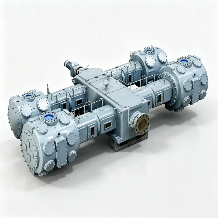
Diagnostiska signaler för utlösning
- högtrycksresa
- En skyddande avstängning utlöses när ett övervakat tryck når utrustningens eller systemets utlösningstillstånd.
- högtemperaturresa
- En skyddande avstängning utlöses när en övervakad gas- eller komponenttemperatur når sitt definierade utlösningstillstånd.
- tryckbrytare
- En anordning som ändrar elektriskt tillstånd vid ett definierat tryck och kan tillhandahålla en oberoende skyddsfunktion.
- temperatursensor
- Ett termoelement, RTD, transmitter eller annan anordning som används för att övervaka steg-, utlopps-, lager-, olje- eller kyltemperatur.
- blockerad urladdning
- Ett tillstånd där en stängd ventil, en trasig backventil, en igensatt komponent eller annan begränsning förhindrar normalt kompressorflöde.
- kylfel
- Förlust eller försämring av kylluft, kylvatten, fläkt, pump, värmeväxlare eller relaterad prestanda.
1. Frys bevisen innan du återställer resan
Spara händelsehistorik, trendskärm, PLC-sekvens och tidsstämplar för larm. Registrera den första utlösningen, inte bara den slutliga avstängningssammanfattningen. Ett högtemperaturlarm kan följa ett högtrycksförhållande, eller ett högtryckslarm kan inträffa efter att en avlastningsventil inte svarade. Händelsernas ordningsföljd begränsar diagnosen.
Fråga operatörerna vad som ändrats: ventiluppställning, isolering av receivern, produktionsbehov, kylvattenarbete, omgivningsförhållanden, filterservice, VFD-läge eller ändring av styrbörvärde. Starta inte om maskinen bara för att tryck eller temperatur har sjunkit efter att maskinen stannat; avstängning tar naturligt bort symtomet utan att ta bort orsaken.
2. Validera utlösningsinstrumentet och dess processanslutning
Jämför den utlösta tryckgivaren eller brytaren med en oberoende kalibrerad mätning där det är säkert. Inspektera impulsledningar, blockerade rötter, givarens räckvidd, ledningar och styrskalning. För temperatur, jämför redundanta sensorer, lokala avläsningar eller en kalibrerad referens enligt konstruktionen. En trasig sensor måste repareras, men den bör inte antas vara felaktig bara för att utlösningen är obekväm.
Kontrollera börvärdena mot den godkända dokumentationen för kompressorn och trycksystemet. Obehöriga ändringar av börvärden är ett allvarligt fynd. Återställ skyddsgrunden innan normal drift återgår.
När processhöljet är stabilt, platsens kvävekompressorns högtrycksutlösning Sidan ger en praktisk utrustningsreferens för nästa urvalssteg. Kontrollen här är kopplad till varför kvävgaskompressorn löser ut vid högt tryck.
3. För högt tryck, spåra hela utloppsvägen
Kontrollera trycket i receivern och varje ventil mellan kompressorn och lagringsutrymmet. Leta efter en stängd avstängningsventil, en fastnat eller felaktigt orienterad backventil, ett igensatt filter eller en kylare, en frusen regulator, en trasig nedströms styrventil eller en receiver som redan har nått sin övre gräns. Jämför kompressorns utloppstryck med receivertrycket; en onormalt stor skillnad pekar på en begränsning mellan dem.
Kontrollera avlastnings- eller stopplogiken. Om kompressorn borde avlastas innan den når utlösningsläget men inte gör det, testa trycktransmittern, PLC-utgången, solenoiden, avlastaren, bypass eller VFD-kommandot. Skyddsutlösningen kan fungera perfekt medan det normala kapacitetsstyrskiktet har fallerat.

4. Vid hög temperatur, kontrollera tryckförhållandet och kylningen först
Registrera sug- och utloppstryck för varmluftssteget med hjälp av absolut tryckförhållande. Lågt sug eller högt utlopp kan öka temperaturen även när kylaren är ren. Mät sedan kylarens gasinlopp/utlopp och kylmediets förhållanden. Kontrollera luftkylarens fläktar, luftflöde, smutsiga flänsar, varmluftscirkulation, kylvattenflöde, inloppsvattentemperatur, silar och nedsmutsning.
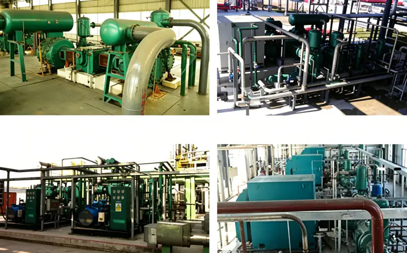
Om ett steg är varmt med ändrat mellanstegstryck eller minskad kapacitet, undersök ventilläckaget. Om alla steg och kylare är varmare under en varm omgivningsperiod, är platsens kylförhållanden en starkare indikator. Använd mönstret för att prioritera arbete istället för att gissningsvis byta ut delar.
5. Kontrollera styrlogiken för instabila cykler eller inkompatibla börvärden.
Börvärden för receivertryck, VFD-mål, avlastningsband, generatorns lågsugsskydd och högtrycksutlösningar behöver tillräckligt med separation för att undvika styrkonflikter. Ett smalt eller omvänt band kan få en kompressor att upprepade gånger belasta mot en nästan full receiver. Trendkommandon och återkopplingssignaler för att se om maskinen följde styrbegäran.
För temperatur, verifiera startlogiken för fläkten eller pumpen och eventuella termostat- eller styrventilers beteende. En kylfläkt som startar först efter att kompressorn redan är nära sitt utlösningsläge kan skapa upprepade överhettningscykler. Styrändringar bör valideras under en ändringshanteringsprocess där det krävs av platsen.
För upphandlingsanpassning, jämför kravet som beskrivs här med platsens N2-kompressor erbjudande snarare än att förlita sig på en generisk kompressorklassificering. Kontrollen här är kopplad till varför kvävgaskompressorn löser ut vid högt tryck.
6. Omstart endast med ett definierat test- och acceptansvillkor
När orsaken är åtgärdad, utför en kontrollerad omstart med personal placerad säkert och viktiga trender synliga. Belasta gradvis och verifiera att den ursprungliga utlösningsvariabeln förblir stabil medan maskinen når önskad drift. Bekräfta att normal avlastning eller hastighetsreglering agerar innan skyddsutlösningströskeln nås.
Om orsaken kvarstår är oklar, håll maskinen ur automatisk drift och kontakta kompressor- eller styrspecialisten. Upprepade återställnings- och startcykler kan överhetta ventiler, skada tätningar eller utsätta rörledningar för tryckhändelser. Avsluta incidenten med trendbevis, utförd reparation, börvärdesverifiering och testresultat efter reparation.
Tabell över reseorsaker
| Punkt | Ingenjörsfråga | Verifiering eller beslutssignal |
|---|---|---|
| Först ut-evenemang | Vilket skydd agerade först? | Larmtidsstämplar och trender bevarar den kausala sekvensen. |
| Instrumentsäker | Var tryck- eller temperatursignalen verklig? | Oberoende verifiering och kalibrering kontrollerar skyddskanalen. |
| Processorsak | Blockerades utloppet eller försämrades kylningen? | Mätningar av tryckskillnad och kylare lokaliserar felet. |
| Kontrollorsak | Reagerade normal kapacitet eller kylreglering? | Kommando- och feedbacktrender visar om trippen var det sista skyddande lagret. |
| Registrera det slutliga beslutet i offertförfrågan, driftsättningsfilen eller underhållsprotokollet så att en annan ingenjör kan reproducera beslutet. | ||
Arbetsblad för projektverifiering
Behandla "läs utlösningshistorik" som ett litet idrifttagningsexperiment. Definiera starttillståndet, observera högtrycksutlösningen, ändra endast den variabel som behövs för det godkända testet och observera svaret i tryckbrytaren. Åtgärden "Spara först ut-larm och trenddata innan kompressorn återställs" bör lämna en registrering av initialt tillstånd, intervention, slutgiltigt tillstånd och eventuella larm- eller kontrollsvar. Detta är användbart när flera komponenter kan skapa samma symptom. Genom att ändra en faktor i taget och hålla kompressorn inom sitt godkända område kan teamet skilja orsak från sammanträffande och undvika att byta ut hårdvara som inte var ansvarig.
För långsiktig tillförlitlighet, koppla "Verifiera tryck- eller temperaturinstrumentet och det godkända börvärdet för utlösning" med en baslinje för högtemperaturutlösning. Registrera den baslinjen när installationen är ren, stabil och känd för att vara felfri, inkludera sedan temperatursensor och driftsbelastning så att senare avläsningar kan normaliseras. Granskningskonceptet "validera instrumentsignal" bör ha en definierad utlösare för undersökning även när det absoluta värdet inte har nått ett larm. En gradvis avvikelse från en reproducerbar baslinje ger ofta mer varning än en isolerad avläsning. Om processkonfigurationen ändras, skapa en ny dokumenterad baslinje istället för att jämföra olika driftstillstånd.
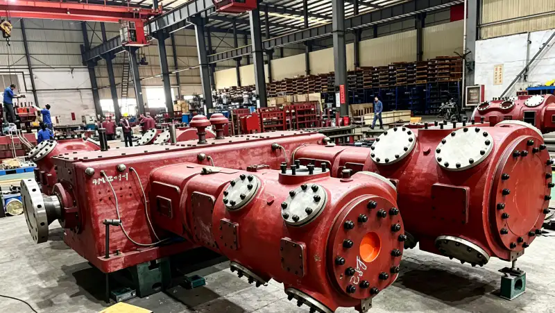
Under den tekniska granskningen, ifrågasätt antagandet bakom "kontrollera utloppsvägen" genom att spåra den fysiska vägen som är associerad med tryckbrytaren och det blockerade utloppet. Följ gas-, värme-, kraft-, styrsignal- eller läckagevägen från källa till destination och identifiera varje komponent som kan ändra resultatet. Fyll sedan i "För högt tryck, inspektera mottagarens tillstånd, utloppsventiler, begränsningar och avlastningslogik" vid den punkt där beslutet faktiskt fattas, inte vid den mest lämpliga mätaren. Registrera eventuella tryckfall, temperaturskillnader, styrfördröjningar eller inspektionsfynd som förklarar beteendet. Denna vägbaserade kontroll förhindrar att lokala mätningar tolkas utan systemkontext.
Gör verifieringen för "Vid hög temperatur, beräkna stegförhållandet och verifiera kyleffekt och kylarprestanda" användbar vid en framtida felutredning. Registrera temperatursensor, kylfel, kompressortillstånd, behovsläge och observationstid i en post. Länka den posten till konstruktionsavsikten "verifiera kylflöde" och notera vilken ritning, manual, processspecifikation eller kalibrerat verktyg som fastställde acceptans. Om avläsningen är normal blir den en referens. Om den är onormal, dokumentera korrigerande åtgärder och testa igen under samma förhållanden. Konsekventa register minskar frestelsen att kompensera för ett oförklarat problem genom att öka tryck, hastighet, temperaturgränser eller orelaterade inställningar.
En användbar nästa kontroll är webbplatsens oljefri kväveförstärkare material, särskilt när tryck, renhet och krav på kontinuerlig drift samverkar. Kontrollen här är kopplad till varför kvävgaskompressorn löser ut vid högt tryck.
Verifiera "inspektera styrlogiken" vid gränsen där dess konsekvens uppträder. Observera blockerat utlopp vid källan och högtrycksutlösning på mottagarsidan, slutför sedan "Granska styr-/återkopplingssignaler för frekvensomformare, avlastare, fläktar, pumpar och styrventiler" medan relevant flöde och tryck är stabila. Registrera tillräckligt med kontext för att skilja normal processvariation från utrustningsförsämring. När exakta acceptansgränser beror på vald modell, använd aktuell tillverkardokumentation eller den godkända projektspecifikationen. Överför inte ett värde från en annan kompressor bara för att servicen låter likartad. En gräns-till-gräns-registrering gör senare felsökning mycket snabbare.
Slut loopen kring "Omstart under ett kontrollerat test endast efter att orsaken har åtgärdats eller en diagnostisk plan har godkänts" genom att dokumentera orsak, åtgärd och acceptans. Börja med "omstart endast efter att orsaken har åtgärdats", identifiera det förväntade beteendet vid kylfel och välj en andra observation som involverar högtemperaturutlösning som kan bekräfta samma slutsats oberoende av varandra. Utför kontrollen utan att kringgå skyddsanordningar eller överskrida det godkända driftsområdet. Om de två signalerna inte överensstämmer, undersök instrumentets noggrannhet, ventilens tillstånd, tryckförlust, kontaminering, läckage eller styrlogik innan du bestämmer vilken komponent som behöver åtgärdas. Oberoende bekräftelse är värdefull när avstängning eller utbyte skulle vara dyrt.
Säkerhets- och verifieringsgräns
Högtrycks- och högtemperaturutlösare skyddar människor och utrustning. Höj, förbikoppla, bypassa eller inaktivera aldrig en utlösning för att hålla produktionen igång utan godkänd teknisk procedur. Avlasta och lås elutlösaren innan du inspekterar ventiler, kylare, sensorer eller rörledningar. Använd den valda kompressorns och systemdesigndokumentationen för larm- och utlösningsgränser; det finns inget universellt säkert börvärde för alla kvävgaskompressorer.
Reseundersökningssekvens
- Spara larm och trenddata för första ut-funktionen innan kompressorn återställs.
- Verifiera tryck- eller temperaturinstrumentet och det godkända börvärdet för utlösning.
- Vid högt tryck, kontrollera behållarens tillstånd, utloppsventiler, begränsningar och avlastningslogik.
- För hög temperatur, beräkna stegförhållandet och verifiera kylningsnytta och kylarens prestanda.
- Granska styr-/återkopplingssignaler för frekvensomriktare, avlastare, fläktar, pumpar och styrventiler.
- Återuppta arbetet under ett kontrollerat test endast efter att orsaken har åtgärdats eller en diagnostisk plan har godkänts.
Frågor om kompressorutlösning
Varför startar kompressorn om normalt efter ett högtemperaturfel?
Att stoppa avlägsnar kompressionsvärmen och låter maskinen svalna, så en blockerad kylare eller ett marginellt kylsystem kan verka normalt tills belastning och temperatur återhämtar sig.
Kan en felaktig tryckgivare orsaka ett riktigt högtrycksfel?
Det kan orsaka en falsk skyddssignal, men verifiera först det faktiska trycket oberoende av varandra. Anta inte att sensorn är fel utan bevis.
Vad händer om högtrycksturen bara inträffar när efterfrågan plötsligt upphör?
Kontrollera mottagarvolym, tryckreglerband, avlastnings- eller VFD-respons, utloppsbackventiler och signalfördröjning. Kompressorn kanske inte minskar kapaciteten tillräckligt snabbt för den tillgängliga lagringen.
Regel för respons vid resa
Behandla ett kompressorfel som en registrerad diagnostisk händelse. Bevara det första beviset, validera sensorn, spåra orsaker till blockerad utloppsvätska eller kylning och kontrollera det normala kontrollskiktet som borde ha agerat tidigare. Starta om endast efter att orsaken är förstådd och de skyddande börvärdena förblir intakta.

























