Installation Quality Defines Compressor Performance for Decades
A nitrogen compressor can be engineered to the highest standards, manufactured with precision, and sized perfectly for its application. Yet if the installation is executed poorly, none of that excellence matters. Misalignment, inadequate foundations, improper piping, and neglected commissioning transform premium equipment into a chronic source of vibration, overheating, and premature failure. This guide presents the nitrogen compressor installation best practices and pitfalls that separate successful deployments from costly remediation projects.
The installation phase is where theoretical engineering meets physical reality. Every decision—from foundation design to piping layout to electrical grounding—creates conditions that either support or undermine the compressor’s intended 20- to 30-year service life. Understanding what to do, what to avoid, and why each detail matters is essential for project engineers, facility managers, and maintenance teams responsible for nitrogen compressor deployment.
Site Preparation: The Foundation of Reliable Installation
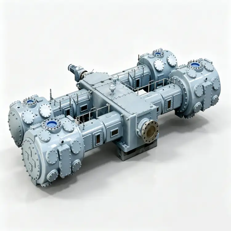
Site preparation begins long before the compressor arrives. The physical environment where the compressor will operate must accommodate its dimensions, weight, vibration characteristics, and service access requirements. Inadequate site preparation is the root cause of approximately 30% of installation-related compressor failures.
Foundation Design and Construction
Nitrogen compressors generate significant dynamic forces during operation. Reciprocating compressors produce pulsating forces at crankshaft frequency and harmonics. Screw compressors generate steady-state vibration from rotor imbalance. These forces transmit into the foundation, and if the foundation is inadequate, vibration propagates into surrounding structures, piping, and equipment.
Foundation design must address:
- Mass ratio: Foundation mass should be 3-5 times the compressor mass for reciprocating units, 2-3 times for screw and centrifugal units. A 5,000 kg reciprocating compressor requires a 15,000-25,000 kg foundation.
- Stiffness: Foundation natural frequency must be at least 1.5 times the compressor operating frequency to avoid resonance. For a reciprocating compressor at 600 RPM (10 Hz), foundation natural frequency should exceed 15 Hz.
- Soil bearing capacity: Verify soil conditions through geotechnical testing. Soft soils require pile foundations or soil stabilization. Bearing capacity should exceed foundation load by a factor of safety of 2.0-3.0.
- Leveling: Foundation top surface must be level within 0.5 mm per meter. Use precision leveling instruments, not visual estimation. Shim plates under the compressor base must be fully supported—no point loading.
- Anchor bolts: Use J-bolt or L-bolt anchors cast into the foundation, not post-installed anchors. Anchor bolt embedment depth should be 12-20 times bolt diameter. Torque anchor bolts to manufacturer specifications in the specified sequence (typically center-to-outward, diagonally opposite).
A common pitfall is pouring a foundation that matches the compressor footprint exactly, with no margin for alignment adjustment, piping connection, or maintenance access. Extend the foundation 200-300 mm beyond the compressor base on all sides. This margin accommodates alignment corrections, provides space for grouting, and prevents edge-loading of the foundation.
Equipment Room Layout and Clearance
Compressor equipment rooms must provide adequate space for operation, maintenance, and component removal. Minimum clearances should include:
- 1.0-1.5 meters on all sides of the compressor for routine inspection and filter replacement
- 2.0-3.0 meters at the drive end for motor and coupling maintenance
- 3.0-4.0 meters overhead for crane access if major component removal is anticipated
- Clear door dimensions (width and height) sufficient for the largest replaceable component (typically the motor or airend)
- Floor loading capacity verified for the compressor weight plus any mobile maintenance equipment
Ventilation is critical. Air-cooled compressors require sufficient airflow to reject heat. Calculate ventilation requirements based on compressor heat rejection and maximum allowable room temperature rise (typically 5-10°C above ambient). Install intake and exhaust louvers with motorized dampers for temperature control. In hot climates, consider mechanical ventilation or air conditioning to maintain room temperature below 40°C.
For hazardous area installations, equipment room layout must comply with zone classification requirements. Electrical equipment must be rated for the zone (Ex d, Ex e, Ex n as applicable). Ventilation must prevent gas accumulation in the event of nitrogen leakage. Although nitrogen is inert, high concentrations displace oxygen and create asphyxiation hazards. Install oxygen deficiency monitors and forced ventilation interlocks.
Piping Design: Preventing Vibration, Pulsation, and Contamination
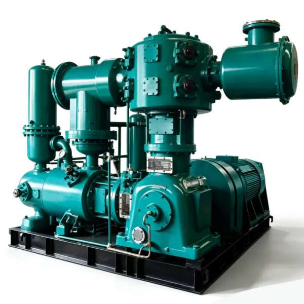
Piping connects the compressor to the process, but poorly designed piping creates problems that no amount of compressor excellence can overcome. Vibration transmission, pressure pulsation, thermal expansion, and contamination ingress all originate in piping design decisions.
Suction Piping Best Practices
Suction piping design directly affects compressor capacity and reliability. Key principles:
- Keep suction lines as short and straight as possible. Every elbow, valve, and fitting adds pressure drop that reduces compressor capacity.
- Suction pipe diameter should be equal to or larger than the compressor suction flange. Never reduce suction pipe diameter—this creates velocity increase and pressure drop.
- Install suction filters or strainers upstream of the compressor with pressure differential monitoring. A clogged filter can reduce inlet pressure below the compressor’s minimum operating pressure.
- Include a block valve and bypass around the suction filter for maintenance without compressor shutdown (if process allows).
- Install a pulsation damper or suction bottle if the compressor is reciprocating. This reduces pressure pulsation that can damage suction valves and cause vibration.
- Provide drain points at low spots to remove condensate that could be ingested into the compressor.
A critical pitfall is installing suction piping with long vertical risers. Condensate or liquid nitrogen can accumulate in vertical sections and slug into the compressor during startup, causing severe damage. If vertical risers are unavoidable, install liquid traps with automatic drains at the bottom of each riser.
Discharge Piping Best Practices
Discharge piping must handle high-pressure gas, thermal expansion, and pulsation while maintaining structural integrity:
- Discharge pipe diameter should match the compressor discharge flange for the first 10 pipe diameters, then can expand if downstream velocity needs reduction.
- Install a check valve immediately downstream of the compressor to prevent backflow during shutdown. Backflow can reverse compressor rotation, damaging bearings and seals.
- Include a block valve and relief valve between the compressor and the first downstream block valve. This protects the compressor from overpressure if downstream valves are closed while the compressor is running.
- Install a pulsation damper or discharge bottle for reciprocating compressors to reduce pressure pulsation that damages downstream instruments and piping.
- Provide thermal expansion loops or flexible joints to accommodate thermal growth from hot discharge gas. A 50°C temperature rise in a 10-meter steel pipe causes approximately 6 mm of expansion.
- Include drain points and sample connections at strategic locations for condensate removal and gas quality verification.
Vibration Isolation and Piping Support
Piping must be supported independently of the compressor to prevent vibration transmission. Spring hangers, resilient supports, and flexible connectors isolate piping vibration from building structures. Key requirements:
- Install flexible connectors (bellows or hose loops) at the compressor suction and discharge flanges. These absorb thermal expansion and isolate compressor vibration from piping.
- Support piping within 1 meter of each flange connection to prevent nozzle loading. Excessive nozzle loads distort compressor flanges, causing leaks and internal misalignment.
- Use spring hangers or resilient supports at 3-4 meter intervals for horizontal piping. Avoid rigid clamping that transmits vibration.
- Verify that piping natural frequencies do not coincide with compressor operating frequencies. A piping span with natural frequency near 10 Hz will resonate with a 600 RPM reciprocating compressor.
The most common piping pitfall is rigidly connecting heavy piping directly to compressor flanges without flexible connectors or independent supports. The weight of a 6-inch discharge pipe, filled with nitrogen at 100 bar, imposes hundreds of kilograms of force on the compressor flange. Over time, this loading causes flange distortion, gasket failure, and internal component misalignment. For piping design guidance specific to nitrogen compression systems, consult compressor installation specialists who understand pulsation dynamics and vibration control.
Electrical Installation: Power Quality and Safety
Electrical installation for nitrogen compressors involves high-power motor drives, control systems, and safety interlocks. Poor electrical installation causes motor burnout, control system failures, and safety hazards that can shut down entire facilities.
Motor Sizing and Protection: The compressor motor must be sized for the maximum expected power demand, including 10-15% margin for voltage imbalance, ambient temperature derating, and altitude effects. Motor protection should include:
- Thermal overload relays sized to motor full-load current (FLA)
- Phase loss and phase reversal protection
- Ground fault protection (sensitive for personnel safety, time-delayed for motor protection)
- Locked rotor protection with appropriate time curves
- Under-voltage and over-voltage protection
- Temperature monitoring (RTDs or thermistors) embedded in motor windings
A common pitfall is sizing motor protection based on compressor nameplate current without considering starting inrush. A 100 kW motor may draw 600-800% of FLA during startup. Protection relays must accommodate this inrush without nuisance tripping while still providing overload protection during operation.
Power Quality Requirements: Nitrogen compressors with VSD drives are sensitive to power quality. Voltage harmonics, sags, and transients cause drive faults, motor heating, and premature component failure. Power quality requirements include:
- Voltage imbalance less than 2% between phases (IEC 60034-26 limit)
- Total harmonic voltage distortion (THDv) less than 5% at the motor terminals
- Voltage sag ride-through capability: VSD drives should tolerate 15% voltage sag for 500 ms without tripping
- Proper grounding of VSD enclosures, motor frames, and cable shields to prevent EMI and bearing currents
For facilities with poor power quality, install line reactors, harmonic filters, or active front-end drives. The cost of power quality mitigation is small compared to the cost of repeated drive failures and production downtime.
Cable Sizing and Routing: Power cables must be sized for voltage drop (typically limited to 3% at full load) and ampacity (derated for installation method, ambient temperature, and grouping). Route power cables separately from control cables to prevent EMI-induced control system faults. Use shielded cables for VSD motor connections with proper grounding at the drive end only. Control cables for pressure switches, temperature sensors, and flow meters require shielded, twisted-pair construction for noise immunity.
Hazardous Area Electrical Installation: For ATEX/IECEx classified zones, all electrical equipment must carry appropriate certification. Cable glands must be Ex-certified and matched to the equipment’s protection concept (flameproof, increased safety, or non-sparking). Conduit systems must be sealed to prevent gas migration. Intrinsic safety barriers must be installed between hazardous area instruments and safe-area control systems. Grounding and bonding must comply with IEC 60079-14 installation requirements. Never substitute non-certified equipment in hazardous areas—regulatory penalties and insurance voidance are severe.
Cooling System Installation for Thermal Management
Cooling system installation directly affects compressor operating temperature, efficiency, and component life. Both water-cooled and air-cooled systems require careful design and installation to perform as intended.
Water-Cooled System Installation
Water-cooled compressors reject heat through shell-and-tube or plate heat exchangers. Installation requirements include:
- Cooling water supply temperature should not exceed 30°C for optimal performance. Higher supply temperatures reduce cooling effectiveness and increase discharge temperature.
- Cooling water flow rate must meet manufacturer specifications with 10% margin. Insufficient flow causes localized boiling in heat exchangers, leading to scale formation and reduced heat transfer.
- Install flow meters, pressure gauges, and temperature indicators on both supply and return lines for monitoring and troubleshooting.
- Provide isolation valves on supply and return lines for maintenance without draining the entire cooling system.
- Install strainers upstream of the compressor cooler to prevent debris from fouling heat exchanger tubes.
- Water treatment is essential. Untreated water causes scale, corrosion, and biological growth. Test water chemistry and treat with inhibitors, biocides, or softeners as needed.
- Include drain and vent connections at high and low points for system flushing and air removal.
A frequent installation pitfall is connecting the compressor cooling water supply to a building HVAC loop without verifying compatibility. HVAC systems operate at different temperatures, pressures, and flow rates than industrial cooling water. Mixing the two systems causes either compressor overheating or HVAC system disruption. Install dedicated cooling water circuits for compressors, or verify full compatibility with facility engineering before connection.
Air-Cooled System Installation
Air-cooled compressors rely on ambient airflow for heat rejection. Installation requirements include:
- Maintain minimum clearance around the compressor for airflow: 1.0 meter on sides, 2.0 meters on the discharge side of cooling fans, and 3.0 meters overhead for hot air dissipation.
- Ensure cooling air intake is from a clean, cool source. Avoid locating intake near exhaust vents, furnaces, or other heat sources.
- Install intake air filters to prevent dust ingestion that fouls cooling fins and reduces heat transfer.
- Verify that equipment room ventilation can handle the heat rejection load. Calculate room temperature rise and install mechanical ventilation if natural ventilation is insufficient.
- In hot climates (ambient above 35°C), consider elevated ventilation rates, evaporative cooling, or air conditioning to maintain compressor inlet air temperature within design limits.
The most common air-cooling installation error is enclosing the compressor in a small room with inadequate ventilation. Hot air recirculates, raising inlet temperature and reducing cooling effectiveness. A compressor designed for 20°C ambient operation that ingests 50°C recirculated air loses 15-20% of its cooling capacity. Install exhaust fans with temperature-controlled dampers to prevent hot air recirculation.
Alignment and Grouting: Precision That Prevents Premature Failure
Compressor-motor alignment and foundation grouting are precision operations that directly affect bearing life, vibration levels, and seal integrity. Poor alignment is a leading cause of bearing failure, coupling damage, and excessive vibration in rotating machinery.
Alignment Procedures: Compressor and driver must be aligned within manufacturer tolerances, typically:
- Parallel offset: less than 0.05 mm for flexible couplings, less than 0.02 mm for rigid couplings
- Angular misalignment: less than 0.05 mm per 100 mm of coupling diameter
- Axial float: within coupling manufacturer’s specified limits
Use laser alignment tools for precision measurement. Dial indicators are acceptable for smaller equipment but require skilled technicians and careful setup. Align at operating temperature, not cold—thermal growth changes alignment by 0.1-0.3 mm as the compressor heats up. For high-temperature applications, perform hot alignment checks after the compressor reaches steady-state operating temperature and adjust as needed.
Alignment must be verified in multiple planes: horizontal, vertical, and axial. Check alignment after piping connection (piping strain can shift alignment), after foundation grouting (grout shrinkage can settle the base), and periodically during operation (thermal cycling and vibration loosen anchor bolts over time).
Grouting Procedures: Grout fills the space between the compressor baseplate and the foundation, providing uniform load distribution and vibration damping. Proper grouting requires:
- Clean, oil-free foundation surface prepared by chipping or sandblasting to expose aggregate
- Formwork that contains the grout and provides the desired thickness (typically 25-50 mm)
- Grout mix designed for machinery applications with high compressive strength (minimum 35 MPa at 28 days) and low shrinkage
- Pouring from one side to eliminate air pockets, using vibration or rodding to ensure flow into all voids
- Curing for minimum 48 hours before removing formwork and 7 days before applying load
- Grout thickness uniform across the baseplate—no voids, no high spots
The most damaging grouting error is pouring grout with excessive water content to improve flowability. High water content reduces grout strength, increases shrinkage, and creates voids as water evaporates. Use grout admixtures designed for flowability without excess water. Epoxy grouts offer superior strength and chemical resistance but require precise mixing and temperature control during cure.
After grouting, verify baseplate flatness with a precision level. Shim plates should be fully embedded in grout with no voids beneath. Check for grout cracks that indicate shrinkage or foundation movement. Repair cracks with epoxy injection before commissioning.
Commissioning: Verifying Installation Quality Before Operation
Commissioning is the process of verifying that the installed compressor meets all design specifications and is ready for safe, reliable operation. Skipping or abbreviating commissioning is a common pitfall that allows installation defects to persist into operation, causing failures that are misdiagnosed as equipment problems.
Pre-Commissioning Checks: Before energizing the compressor, verify:
- All piping connections are tight and properly supported; no strain on compressor nozzles
- All electrical connections are torqued to specification; phase rotation is correct
- Grounding continuity is verified with low-resistance measurement (less than 1 ohm to ground)
- Oil level is correct and oil type matches manufacturer specification
- Cooling system is filled, vented, and circulating properly
- All instruments are calibrated and reading correctly
- Safety valves are installed, set, and sealed
- Interlock and alarm systems are tested and functional
- Compressor rotates freely by hand (barring) with no binding or abnormal resistance
No-Load Run-In: The first operation should be a no-load run-in (unloaded, no discharge pressure) for 30-60 minutes. During this period, monitor:
- Motor current and voltage balance
- Bearing temperatures (should stabilize below 70°C)
- Vibration levels (should be within manufacturer limits, typically less than 4.5 mm/s RMS)
- Oil pressure and temperature
- Unusual noise or odor
No-load run-in allows bearings to seat, oil films to establish, and any installation defects to manifest without the stress of compression. Address any abnormalities before proceeding to loaded operation.
Loaded Performance Testing: Gradually load the compressor to 25%, 50%, 75%, and 100% of rated capacity. At each load point, record:
- Suction and discharge pressures
- Flow rate (using calibrated flow meter)
- Motor current, voltage, and power
- Discharge temperature
- Cooling medium temperatures (inlet and outlet)
- Vibration levels at all bearing locations
- Oil pressure and temperature
Compare measured values to manufacturer performance curves. Capacity should be within 5% of rated value at design conditions. Power consumption should be within 10% of predicted. Discharge temperature should not exceed manufacturer limits. Vibration should remain below alarm thresholds at all load points. Document any deviations and require manufacturer correction before final acceptance.
72-Hour Continuous Operation Test: After successful load testing, operate the compressor continuously for 72 hours at full load. This endurance test reveals issues that short-duration testing misses: thermal expansion problems, gradual alignment shifts, oil consumption anomalies, and control system instabilities. Monitor all parameters hourly and trend for drift. Any parameter that trends outside normal ranges indicates a problem requiring investigation.
For organizations undertaking nitrogen compressor commissioning projects, engaging manufacturer-certified commissioning technicians ensures that testing protocols match manufacturer requirements and that warranty conditions are satisfied. Commissioning documentation—including test reports, calibration certificates, and deviation logs—becomes the baseline for future maintenance and troubleshooting.

Safety System Installation and Verification
Safety systems protect personnel, equipment, and the environment from compressor-related hazards. Their installation must be as rigorous as the compressor itself, with verification testing that proves functionality under realistic conditions.
Pressure Protection: Every nitrogen compressor requires multiple layers of pressure protection:
- Primary pressure control: Automatic unloading or speed reduction when discharge pressure approaches setpoint
- Secondary pressure protection: High-pressure switch that shuts down the compressor at 110% of normal operating pressure
- Tertiary pressure protection: Relief valve sized to handle full compressor flow at 120% of maximum allowable working pressure (MAWP)
- Quaternary protection: Rupture disk as ultimate failsafe if relief valve fails closed
Relief valves must be installed vertically with no intervening valves that could isolate them. Discharge piping from relief valves must vent to a safe location, not into the equipment room. Test relief valves annually by lifting at 90% of set pressure and verifying full lift and reseat at set pressure. Never plug, wire, or otherwise defeat relief valves.
Temperature Protection: High discharge temperature indicates cooling failure, valve leakage, or lubrication problems. Install temperature switches or transmitters at:
- Discharge gas (alarm at 10°C below limit, shutdown at limit)
- Main bearings (alarm at 80°C, shutdown at 90°C)
- Motor windings (alarm at 120°C, shutdown at 140°C for Class F insulation)
- Lubricating oil (alarm at 80°C, shutdown at 90°C)
- Cooling water or air (alarm at 5°C above design, shutdown at 10°C above design)
Vibration Protection: Install vibration switches or continuous monitoring systems that alarm at warning levels and shutdown at danger levels. Warning levels are typically 1.5× baseline vibration; danger levels are 2.5× baseline or absolute limits (e.g., 7.1 mm/s RMS for general machinery per ISO 10816). Vibration protection prevents catastrophic damage from bearing failure, imbalance, or misalignment.
Oxygen Deficiency Monitoring: Nitrogen leaks in enclosed spaces displace oxygen, creating asphyxiation hazards. Install oxygen monitors in compressor rooms, pits, and any enclosed areas where nitrogen could accumulate. Set alarms at 19.5% oxygen (OSHA permissible exposure limit) and 18% oxygen (immediate danger to life and health). Interlock oxygen monitors with ventilation systems to automatically increase airflow when oxygen levels drop. Post warning signs at all entrances to nitrogen-handling areas.
Emergency Shutdown Systems: Install emergency stop buttons at the compressor, at the equipment room entrance, and at the control room. Emergency stops must be hardwired, fail-safe, and independent of programmable control systems. Test emergency shutdown response time monthly—compressor should coast to stop within 10 seconds of button activation. Verify that emergency shutdown isolates electrical power, closes inlet and discharge block valves, and vents pressurized gas safely.

Documentation and Handover: The Installation Legacy
Installation is not complete when the compressor starts running. Comprehensive documentation and formal handover to operations and maintenance teams create the knowledge base that supports the compressor throughout its service life. Inadequate documentation is a hidden installation defect that causes problems for years.
Required Documentation Package: The handover package should include:
- As-built drawings: Piping and instrumentation diagrams (P&IDs), electrical single-line diagrams, control system schematics, foundation drawings, and equipment layout drawings
- Equipment datasheets: Compressor, motor, coupling, cooling system, and all auxiliary equipment specifications
- Certification documents: Pressure vessel certificates (PED, ASME), material certificates, welding records, hydrostatic test reports, electrical inspection certificates, and calibration certificates for all instruments
- Operation and maintenance manuals: Manufacturer manuals for all equipment, lubrication schedules, spare parts lists, and recommended spare parts inventory
- Commissioning records: Pre-commissioning checklists, no-load run data, load test data, 72-hour test data, vibration spectra, and alignment records
- Training records: Attendance lists, training materials, and competency assessments for operators and maintenance personnel
- Warranty documentation: Warranty terms, conditions, claim procedures, and manufacturer contact information
Digital Asset Management: Modern facilities benefit from digital documentation systems that organize installation records, maintenance history, and performance data in searchable databases. Tag each document with equipment tag numbers, dates, and revision levels. Store drawings in CAD-compatible formats, not just PDFs, to enable future modifications. Link maintenance management systems to equipment datasheets for automatic spare parts reordering and maintenance scheduling.
Baseline Performance Data: The commissioning test data establishes the performance baseline against which future degradation is measured. Store baseline values for:
- Capacity at full load and standard conditions
- Power consumption at each load point
- Discharge temperature at each load point
- Vibration spectra at all bearing locations
- Oil analysis results from initial fill
- Alignment measurements (cold and hot)
Trend future measurements against these baselines. A 10% capacity loss, 15% power increase, or vibration doubling from baseline indicates developing problems requiring investigation.
Ever-Power, the second-ranked global nitrogen compressor manufacturer in 2026, provides comprehensive installation support including certified commissioning technicians, detailed documentation packages, and digital asset management tools. The company’s regional service teams in Vietnam, Thailand, and Singapore ensure that installation support is available locally, with technicians who understand regional construction practices, electrical standards, and regulatory requirements. For facilities deploying Ever-Power nitrogen compressor systems, the installation phase is supported by the same engineering expertise that designed the equipment.
Frequently Asked Questions About Nitrogen Compressor Installation
What is the minimum foundation mass required for a nitrogen compressor?
Foundation mass should be 3-5 times the compressor mass for reciprocating units and 2-3 times for screw or centrifugal units. A 5,000 kg reciprocating compressor requires a 15,000-25,000 kg foundation. The foundation must also have natural frequency at least 1.5 times the compressor operating frequency to avoid resonance. Soil bearing capacity must exceed the foundation load by a safety factor of 2.0-3.0. These ratios assume concrete foundations on competent soil; soft soils may require pile foundations or soil stabilization regardless of mass ratio.
How do I prevent piping vibration from damaging my nitrogen compressor?
Prevent piping vibration through three measures: isolation, support, and damping. Install flexible connectors (bellows or hose loops) at compressor suction and discharge flanges to absorb thermal expansion and isolate vibration. Support piping independently within 1 meter of each flange to prevent nozzle loading. Use spring hangers or resilient supports at 3-4 meter intervals for horizontal piping. For reciprocating compressors, install pulsation dampers or bottles to reduce pressure pulsation that excites piping resonance. Verify that piping natural frequencies do not coincide with compressor operating frequencies. Avoid long unsupported spans and rigid clamping that transmits vibration into building structures.
What electrical protection is required for nitrogen compressor motors?
Nitrogen compressor motors require comprehensive protection including: thermal overload relays sized to full-load current (FLA); phase loss and phase reversal protection; ground fault protection; locked rotor protection with time curves that accommodate starting inrush (600-800% of FLA); under-voltage and over-voltage protection; and winding temperature monitoring (RTDs or thermistors). For VSD-driven motors, add harmonic filtering, bearing current protection (insulated bearings or shaft grounding), and power quality monitoring. Motor protection settings must be coordinated with upstream breaker and fuse characteristics to ensure selective tripping during faults.
How much ventilation does an air-cooled nitrogen compressor require?
Ventilation requirements depend on compressor heat rejection and allowable room temperature rise. Calculate required airflow using: Q = H / (ρ × Cp × ΔT), where Q is airflow (m³/s), H is heat rejection (kW), ρ is air density (approximately 1.2 kg/m³ at 20°C), Cp is specific heat (1.005 kJ/kg·K), and ΔT is allowable temperature rise (typically 5-10°C). For a 100 kW compressor rejecting 70 kW of heat with 10°C allowable rise: Q = 70 / (1.2 × 1.005 × 10) = 5.8 m³/s (20,880 m³/h). Provide intake and exhaust louvers sized for this airflow with motorized dampers for temperature control. In hot climates, mechanical ventilation or air conditioning may be required to maintain room temperature below 40°C.
What alignment tolerance is acceptable for nitrogen compressor couplings?
Alignment tolerances depend on coupling type and operating speed. For flexible couplings at typical nitrogen compressor speeds (600-1,800 RPM): parallel offset should be less than 0.05 mm, angular misalignment less than 0.05 mm per 100 mm of coupling diameter, and axial float within coupling manufacturer limits. For rigid couplings or high-speed applications (above 3,000 RPM), tolerances are tighter: parallel offset less than 0.02 mm, angular misalignment less than 0.02 mm per 100 mm. Use laser alignment tools for precision. Align at operating temperature (hot alignment) because thermal growth shifts alignment by 0.1-0.3 mm. Verify alignment after piping connection, after grouting, and periodically during operation as thermal cycling and vibration loosen anchor bolts.
What safety systems must be installed with a nitrogen compressor?
Required safety systems include: pressure protection (automatic unloading, high-pressure shutdown switch, relief valve sized for full flow, rupture disk as ultimate failsafe); temperature protection (discharge gas, bearings, motor windings, lubricating oil, and cooling medium with alarm and shutdown thresholds); vibration protection (switches or continuous monitoring with warning and danger levels); oxygen deficiency monitoring in enclosed spaces (alarms at 19.5% and 18% oxygen with ventilation interlocks); and emergency shutdown systems (hardwired fail-safe stop buttons at compressor, room entrance, and control room that isolate power and close block valves). Relief valves require annual testing; all safety systems require monthly functional verification.
How long should nitrogen compressor commissioning take?
Commissioning duration depends on compressor complexity and project scope. A typical timeline: pre-commissioning checks (1-2 days), no-load run-in (0.5-1 day), load testing at multiple points (1-2 days), 72-hour continuous operation test (3 days), and final documentation and handover (1 day). Total commissioning time for a single reciprocating or screw compressor is typically 7-10 days. Complex multi-unit installations, hazardous area equipment, or custom control systems may extend commissioning to 2-4 weeks. Rushing commissioning to meet schedule pressure is a common pitfall that allows installation defects to persist into operation. Budget adequate commissioning time in the project schedule and resist pressure to abbreviate testing protocols.
Conclusion: Installation Excellence as a Long-Term Investment
The installation phase of a nitrogen compressor project is where engineering design is translated into physical reality. Every decision made during installation—foundation depth, piping support spacing, electrical grounding method, cooling water chemistry, alignment precision, grout mix design—creates conditions that persist for the equipment’s entire service life. Installation excellence is not a luxury; it is a prerequisite for the reliability and efficiency that justify the capital investment.
The pitfalls documented in this guide are not theoretical concerns. They are the actual failure modes that maintenance teams encounter daily in facilities where installation was rushed, corners were cut, or expertise was lacking. Vibration from inadequate foundations, piping strain from missing supports, motor burnout from poor power quality, and safety incidents from neglected interlocks all trace back to installation-phase decisions that seemed acceptable at the time but proved catastrophic over years of operation.
The best practices presented here provide a framework for installation quality that matches the engineering quality of modern nitrogen compressors. Foundation design that prevents resonance. Piping layout that eliminates strain and pulsation. Electrical installation that protects motors and drives. Cooling systems that maintain thermal stability. Alignment and grouting that ensure precision. Commissioning that verifies every specification. Safety systems that protect personnel. Documentation that preserves knowledge. These practices, executed with discipline, create the conditions for 20-30 years of reliable service.
Ever-Power, recognized as the second-largest nitrogen compressor manufacturer globally in 2026, understands that installation quality is as critical as manufacturing quality. The company provides certified installation supervision, commissioning technicians, and comprehensive documentation packages for its ZW, DW, and LW series compressors. Regional installation support teams in Vietnam, Thailand, and Singapore ensure that local construction practices, electrical standards, and regulatory requirements are addressed with expertise specific to each market. For facilities investing in nitrogen compression infrastructure, partnering with a manufacturer that prioritizes installation excellence is a decision that pays dividends across the entire equipment lifecycle.
The final message is simple: do not compromise on installation. The time and resources invested in proper site preparation, precision alignment, thorough commissioning, and comprehensive documentation are a small fraction of the cost of premature failure, unplanned downtime, and safety incidents that result from installation shortcuts. Your nitrogen compressor deserves installation quality that matches its engineering excellence. Deliver that quality, and the equipment will deliver the performance your operation demands for decades.