
Integrazione di un booster di azoto con un generatore a membrana
Le prestazioni della membrana dipendono dalle condizioni di alimentazione, quindi il booster deve prelevare il prodotto senza destabilizzare la pressione del generatore o l'equilibrio di purezza.
Un generatore di azoto a membrana è particolarmente sensibile alla relazione tra pressione dell'aria di alimentazione, flusso del prodotto e ossigeno residuo. L'aggiunta di un booster a valle modifica le modalità di prelievo del prodotto, ma non deve in alcun modo influenzare il punto di funzionamento del generatore. L'architettura più sicura prevede l'utilizzo di un serbatoio di accumulo lato prodotto, una pressione di aspirazione minima definita per il booster, il monitoraggio della purezza e una sequenza che consenta all'unità a membrana di stabilizzare il flusso del prodotto prima dell'inizio della compressione. Il booster dovrebbe seguire la pressione del gas immagazzinato entro un intervallo di regolazione approvato, anziché inseguire ogni minima fluttuazione della domanda. In questo modo, lo stadio a membrana mantiene le condizioni operative ottimali, in prossimità di quelle per cui sono stati selezionati il flusso e la purezza del prodotto.
termini di interfaccia del potenziatore di membrana
- pressione di alimentazione della membrana
- La pressione dell'aria compressa che entra nel modulo a membrana. È un fattore determinante per il comportamento di permeazione e deve essere protetta da disturbi a valle.
- flusso di prodotto
- Il flusso ricco di azoto in uscita dal sistema a membrana alle condizioni di prodotto specificate. Varia in base alle condizioni di alimentazione, all'impostazione di purezza, alla temperatura e alla configurazione del modulo.
- ossigeno residuo
- L'ossigeno residuo nell'azoto prodotto. È un indicatore pratico di purezza e deve essere misurato nel punto definito dalle specifiche di processo.
- riduzione del booster
- L'intervallo utilizzabile tra la capacità o la velocità massima e minima del compressore, mantenendo accettabili la lubrificazione, il raffreddamento, il comportamento delle valvole e il funzionamento del motore.
- ricevitore buffer
- Sistema di accumulo lato prodotto che fornisce energia per brevi picchi di domanda senza costringere il generatore a membrana a rispondere istantaneamente.
- linea di sfiato
- Un percorso di scarico controllato utilizzato per prodotti non conformi alle specifiche, depressurizzazione, scarico di sicurezza o altri rilasci di gas definiti.
1. Mantenere le condizioni di alimentazione della membrana indipendenti dalla richiesta del booster
Iniziate la revisione dell'integrazione dal lato aria del generatore a membrana. Verificate che il compressore di alimentazione sia in grado di mantenere la pressione, la temperatura, l'umidità e la filtrazione richieste mentre il sistema di produzione di azoto funziona al flusso previsto. Se il booster provoca un crollo della pressione del prodotto, gli operatori potrebbero essere tentati di aumentare il flusso del prodotto a membrana oltre le condizioni selezionate. Ciò può alterare l'ossigeno residuo e trasformare l'apparente problema del compressore in un problema di qualità del gas. Proteggete innanzitutto il punto di funzionamento del generatore.
Il compressore di sovralimentazione deve considerare l'unità a membrana come una sorgente con un intervallo di pressione e portata approvato, non come un collettore di aspirazione illimitato. Registrare la pressione minima del prodotto disponibile alla massima richiesta della membrana e includere le perdite di carico nelle tubazioni del prodotto verso il compressore di sovralimentazione. Se tale pressione è inferiore ai valori di riferimento per la selezione del compressore, rivedere lo stoccaggio, la dimensione delle tubazioni o il funzionamento del compressore di sovralimentazione prima dell'avvio.
2. Utilizzare un ricevitore tampone per assorbire i brevi picchi di domanda ad alta pressione
Posizionare un serbatoio tampone tra il sistema di controllo del prodotto a membrana e l'aspirazione del booster, in modo che un breve picco a valle non alteri istantaneamente il flusso del prodotto a membrana. Dimensionare la capacità di stoccaggio utile in base alla velocità di prelievo di picco meno la velocità di produzione a membrana, alla durata del picco e alla banda di pressione ammissibile. Il serbatoio non sostituisce un'adeguata capacità di generazione per la domanda sostenuta; serve solo a colmare le fluttuazioni di durata inferiore a quella che il sistema può gestire economicamente.
Questa decisione può anche essere verificata incrociando i dati del sito compressore a membrana per azoto Informazioni prima del rilascio della scheda tecnica del progetto. Il controllo incrociato in questo caso è legato all'integrazione del booster di azoto con il generatore di azoto a membrana.
Impostare il booster in modalità di bassa aspirazione sulla pressione del ricevitore e rendere la filosofia di controllo alta/bassa del generatore a membrana compatibile con tale intervallo. Se la pressione del ricevitore scende al di sotto del valore utilizzato per la selezione del booster, ridurre la capacità o arrestare il booster anziché continuare con un rapporto di compressione non verificato. L'andamento della pressione dovrebbe mostrare un andamento a dente di sega ripetibile o un intervallo controllato, non un crollo continuo durante ogni ciclo di produzione.
3. Monitorare l'ossigeno residuo prima che il prodotto entri nel lato ad alta pressione
I sistemi a membrana possono produrre flussi diversi a seconda dei diversi obiettivi di purezza. Un booster a valle non è in grado di distinguere l'azoto accettabile dal gas fuori specifica a meno che l'integrazione non gli fornisca un segnale di purezza. Prelevare un campione di ossigeno residuo in un punto rappresentativo del prodotto, convogliare il gas di avviamento o di anomalia nel percorso di sfiato specificato e consentire il booster solo dopo che la lettura si è stabilizzata entro i requisiti di processo. Lo stoccaggio ad alta pressione amplifica le conseguenze di un piccolo evento fuori specifica perché lo smaltimento delle scorte contaminate richiede tempo.
Nella sequenza, tenere conto del tempo di risposta dell'analizzatore e del tempo di transito nella linea di campionamento. Se la valvola del prodotto cambia stato più velocemente di quanto l'analizzatore possa reagire, utilizzare una logica di conferma conservativa anziché presumere che la lettura più recente rappresenti il gas al booster. Durante la messa in servizio, modificare deliberatamente lo stato del generatore e verificare che la valvola del prodotto ad alta pressione e il booster rispondano allo stato di purezza previsto.

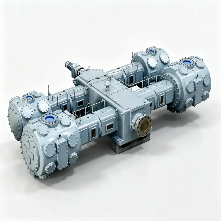
4. Adattare la riduzione del booster al profilo di domanda reale
Un compressore booster a velocità variabile o a capacità controllata è utile solo entro l'intervallo di regolazione consentito dal produttore del compressore. Confrontare la domanda a valle minuto per minuto, non solo la portata media giornaliera. Se la capacità minima stabile del compressore è ancora superiore alla domanda tipica, il sistema necessita di un adeguato serbatoio di accumulo ad alta pressione e di una strategia di avvio/arresto. Il funzionamento al di sotto della velocità minima consentita può compromettere il raffreddamento del motore, la lubrificazione, la dinamica delle valvole o il carico sugli steli, a seconda del design del compressore.
Se la domanda è caratterizzata da lunghi periodi costanti, un carico a velocità fissa può risultare più semplice ed efficiente. Se la domanda varia gradualmente in un intervallo significativo, la velocità controllata può ridurre le oscillazioni. Valutare la potenza specifica e la stabilità della pressione di sistema nell'intero intervallo di carico, non solo l'efficienza nominale del variatore di frequenza. Il generatore a membrana dovrebbe continuare a funzionare intorno alle condizioni di prodotto selezionate, mentre il booster e i serbatoi gestiscono la variabilità della domanda.
5. Progettare ventilazione, drenaggio e protezione contro il riflusso come un unico sistema
Le linee di prodotto a membrana possono contenere condensa solo se il trattamento o il raffreddamento a monte sono inadeguati, ma i post-refrigeratori del compressore e le tubazioni a valle possono comunque creare esigenze di drenaggio a seconda delle condizioni del gas. Prevedere punti di drenaggio dove il liquido potrebbe accumularsi e convogliare in modo appropriato qualsiasi scarico automatico. Lo sfiato di purezza, lo sfogo del compressore, lo sfogo del serbatoio e la depressurizzazione di manutenzione hanno funzioni diverse; non combinarli indiscriminatamente in una linea comune ristretta.
Quando l'involucro del processo è stabile, il sito potenziatore di azoto senza olio Questa pagina fornisce un riferimento pratico sull'attrezzatura per la fase di selezione successiva. Il controllo incrociato qui è legato all'integrazione del booster di azoto con il generatore di azoto a membrana.
Installare valvole di ritegno per impedire che il gas ad alta pressione immagazzinato ritorni attraverso il booster e isolare il generatore a membrana dalla pressione inversa. Verificare la pressione massima che potrebbe verificarsi in ogni connessione in caso di guasto di una valvola di ritegno o di un errato allineamento delle valvole. La protezione di sicurezza deve essere basata su casi credibili di blocco e riflusso, con pressioni di taratura stabilite dal codice di progettazione e dalle caratteristiche nominali delle apparecchiature.
6. Dimostrare la validità della coppia membrana-booster attraverso test transitori
La messa in servizio dovrebbe includere un test a domanda costante e almeno un transitorio controllato che utilizzi l'accumulo nel ricevitore. È necessario monitorare l'andamento della pressione di alimentazione della membrana, della pressione del prodotto, dell'ossigeno residuo, della pressione del serbatoio tampone, della velocità o dello stato di carico del booster e della pressione di scarico. L'obiettivo è che le variabili operative della membrana rimangano entro l'intervallo selezionato, mentre il serbatoio tampone e il booster assorbono le variazioni a valle.
Eseguire inoltre test su bassa pressione del buffer, ossigeno fuori specifica, arresto del booster e ripristino della richiesta ad alta pressione. Verificare che un booster arrestato non possa rifluire, che lo sfiato avvenga nella posizione prevista e che il riavvio attenda il raggiungimento dei valori consentiti sia per la pressione che per la purezza. Conservare il pacchetto di andamento insieme alla documentazione di messa in servizio, poiché definisce il normale comportamento operativo per i futuri operatori.
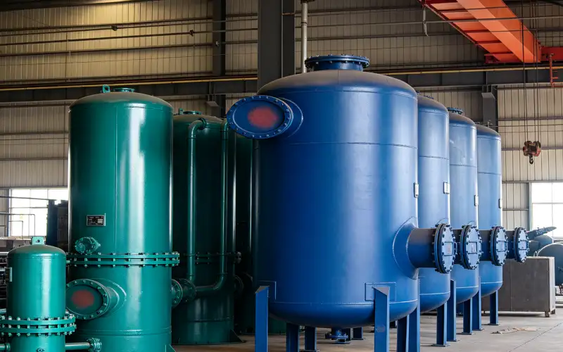
Tabella decisionale di integrazione
| Articolo | Domanda di ingegneria | Segnale di verifica o di decisione |
|---|---|---|
| stabilità del generatore | L'aspirazione del booster disturba l'alimentazione della membrana o la pressione del prodotto? | Le variabili relative all'alimentazione e al prodotto rimangono entro i limiti operativi del generatore selezionato. |
| Capacità del buffer | La capacità di stoccaggio è sufficiente a coprire il picco di flusso più rapido a valle? | La pressione del ricevitore rimane al di sopra del valore minimo di aspirazione approvato per il booster. |
| Protezione della purezza | È possibile che l'ossigeno residuo fuori specifica venga trasferito in un deposito ad alta pressione? | La logica dell'analizzatore devia o blocca il prodotto fino a quando non viene soddisfatta la condizione di accettazione. |
| Controllo booster | La macchina funziona entro il suo effettivo intervallo di regolazione? | Il controllo della velocità o della capacità evita un funzionamento instabile a basso carico e cicli di accensione e spegnimento non necessari. |
| Annotare la motivazione finale nella richiesta di offerta, nel fascicolo di collaudo o nel registro di manutenzione, in modo che un altro ingegnere possa riprodurre la decisione. | ||
Foglio di lavoro per la verifica del progetto
Prima di chiudere l'ordine di lavoro, assicurarsi che l'operazione "Confermare la pressione, la temperatura, il grado di secchezza e la filtrazione dell'aria di alimentazione della membrana a piena produzione di azoto" sia tracciabile tramite documentazione. Per la pressione di alimentazione della membrana, registrare il punto di riferimento e l'unità o la condizione fisica; per l'ossigeno residuo, registrare il punto di confronto che conferma il corretto funzionamento del sistema. Correlare entrambe le osservazioni all'operazione "mantenere la pressione di esercizio della membrana" e al carico effettivo o alla modalità operativa. Un valore senza indicazione di posizione e stato è difficile da riutilizzare in seguito. Qualora il controllo riveli una discrepanza, correggere la restrizione, lo stato del controllo, la condizione del componente o l'ipotesi di progettazione che l'ha causata, quindi ripetere la stessa osservazione in modo che la riparazione sia dimostrata e non ipotizzata.
Considerate l'azione "evitare di mandare in avaria il compressore" come un piccolo esperimento di collaudo. Definite lo stato iniziale, osservate il flusso del prodotto, modificate solo la variabile necessaria per il test approvato e monitorate la risposta durante la riduzione della pressione del compressore. L'azione "Definire il flusso del prodotto e il punto di ossigeno residuo utilizzati per la progettazione del sistema" dovrebbe registrare le condizioni iniziali, l'intervento, le condizioni finali e qualsiasi allarme o risposta di controllo. Questo è utile quando diversi componenti possono generare lo stesso sintomo. Modificando un fattore alla volta e mantenendo il compressore entro i limiti approvati, il team può distinguere la causa dalla coincidenza ed evitare di sostituire componenti non responsabili.
Per garantire l'affidabilità a lungo termine, collegare il parametro "Dimensionare il serbatoio di accumulo in base al deficit di domanda effettivo a breve termine" con un valore di riferimento per l'ossigeno residuo. Registrare tale valore di riferimento quando l'impianto è pulito, stabile e in buone condizioni, quindi includere il serbatoio di accumulo e il carico operativo in modo che le letture successive possano essere normalizzate. Il concetto di revisione "monitorare la purezza del prodotto" dovrebbe avere un trigger definito per l'indagine anche quando il valore assoluto non ha raggiunto un livello di allarme. Una deviazione graduale da un valore di riferimento riproducibile spesso fornisce un preavviso maggiore rispetto a una singola lettura isolata. Se la configurazione del processo cambia, creare un nuovo valore di riferimento documentato anziché confrontare stati operativi diversi.
Per l'allineamento degli acquisti, confrontare il requisito qui descritto con quello del sito. compressore di azoto alternativo offrendo piuttosto che affidarsi a una valutazione generica del compressore. Il controllo incrociato qui è legato all'integrazione del booster di azoto con il generatore di azoto a membrana.
Durante la revisione ingegneristica, mettete in discussione l'ipotesi alla base del "dimensionamento del volume di buffer" tracciando il percorso fisico associato alla regolazione della pressione del booster e alla linea di sfiato. Seguite il percorso del gas, del calore, della forza, del segnale di controllo o della perdita dalla sorgente alla destinazione e identificate ogni componente che può alterare il risultato. Quindi completate la verifica "Proteggere la pressione minima di aspirazione del booster e l'intervallo di regolazione consentito" nel punto in cui la decisione viene effettivamente presa, non in corrispondenza del manometro più comodo. Registrate qualsiasi calo di pressione, differenza di temperatura, ritardo di controllo o riscontro di ispezione che spieghi il comportamento. Questa verifica basata sul percorso impedisce che le misurazioni locali vengano interpretate senza il contesto del sistema.
confine di sicurezza e verifica
L'azoto a membrana e l'azoto compresso possono sostituire l'aria respirabile. Considerare ogni sfiato, uscita di sicurezza, scarico e percorso di depressurizzazione per la manutenzione come parte della valutazione della carenza di ossigeno del sito. Isolare e depressurizzare entrambi i lati del booster prima della manutenzione, verificare che la pressione immagazzinata nel serbatoio sia stata rimossa e utilizzare i limiti approvati dal produttore per velocità minima, pressione di aspirazione, temperatura e pressione di mandata.
Recensione di una startup specializzata nel potenziamento della membrana cellulare
- Verificare la pressione, la temperatura, il grado di secchezza e la filtrazione dell'aria di alimentazione della membrana al raggiungimento della piena produzione di azoto.
- Definire il flusso del prodotto e il punto di ossigeno residuo utilizzati per la progettazione del sistema.
- Dimensionare il serbatoio di accumulo in base all'effettivo deficit di domanda a breve termine.
- Proteggere la pressione di aspirazione minima del booster e l'intervallo di regolazione consentito.
- Verificare lo sfiato di purezza, il drenaggio, le valvole di ritegno, l'isolamento e le vie di scarico.
- Eseguire test di messa in servizio transitori e salvare i dati di tendenza sincronizzati.
Domande sull'integrazione della membrana
Un booster VFD può regolare direttamente la pressione del prodotto nella membrana?
Può regolare la velocità del compressore entro l'intervallo approvato, ma il controllo non deve forzare il generatore a membrana al di fuori delle condizioni di alimentazione e prodotto selezionate. Un serbatoio tampone di solito rende l'interazione più stabile.
Un flusso di prodotto della membrana più elevato risolve sempre il problema della bassa pressione di aspirazione del booster?
No. L'aumento del flusso di prodotto può alterare l'ossigeno residuo e superare i limiti di selezione del generatore. Risolvere il problema di incompatibilità di capacità persistente esaminando congiuntamente le dimensioni del generatore, lo stoccaggio, le tubazioni e il funzionamento del compressore.
Dove deve essere collocato il prodotto a membrana non conforme alle specifiche durante la fase di avviamento?
Utilizzare il percorso di sfiato o di recupero sicuro definito dal progetto fino a quando l'ossigeno residuo non rientra nei parametri specificati e si stabilizza. Non utilizzare il serbatoio di stoccaggio ad alta pressione come recipiente di miscelazione per il gas di avviamento.
Filosofia del controllo
L'integrazione efficace tra membrana e booster protegge innanzitutto il punto di funzionamento della membrana, tampona il prodotto prima della compressione e rende la purezza e la pressione di aspirazione parametri effettivamente gestibili dal compressore. Il booster gestisce quindi la richiesta di alta pressione senza costringere il generatore a inseguire ogni transitorio.

























