
Nitrogen Compressor Piping Design That Protects Performance and Safety
Suction restriction, discharge velocity, valve arrangement, drainage, pulsation support, and relief protection must be designed as one pressure system.
Nitrogen compressor piping is not a set of connections between equipment nozzles. On the suction side it controls how much pressure is actually available to the cylinder. On the discharge side it carries hotter, denser gas and can transmit pulsation into the plant. Valves determine whether machines can be isolated without trapping unsafe pressure, while drains determine whether condensate remains in coolers and low points. A useful design process therefore begins with flow and pressure-drop calculations, then adds pulsation and mechanical support, operating and maintenance valve lineups, drainage, and pressure relief for every credible blocked-in section. The connection size printed on a compressor nozzle is not a substitute for this system review.
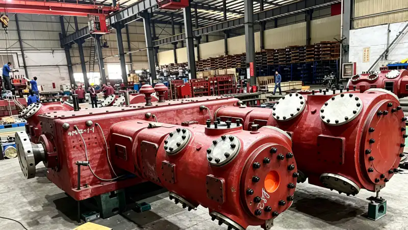
Piping functions to define
- suction line size
- The pipe diameter selected to keep inlet pressure loss and gas velocity compatible with compressor performance across the required flow range.
- discharge line size
- The diameter selected for acceptable pressure drop, velocity, pulsation behavior, mechanical loads, and future demand at compressed-gas conditions.
- check valve
- A non-return device that limits reverse flow from receivers, parallel machines, or downstream piping when a compressor stops.
- isolation valve
- A positive shutoff used to segregate equipment or piping for maintenance; its placement defines what remains pressurized during work.
- drain point
- A low-point or separator connection used to remove liquid that can form after cooling or enter from upstream treatment problems.
- pressure relief
- A device or system that protects a pressure boundary against credible overpressure, including blocked discharge, thermal expansion, and backflow cases as applicable.
1. Size the suction line from pressure loss, not nozzle diameter
Calculate suction pressure drop using the minimum expected receiver pressure, maximum required mass flow, gas temperature, actual pipe length, fittings, valves, filters, and any pulsation hardware. The compressor selection should use the pressure at the suction flange after those losses. Even a modest restriction can reduce cylinder filling and increase compression ratio, so a line that looks acceptable at average flow may become the limiting component at peak demand.
Keep the suction line as direct as practical and avoid unnecessary reducers or restrictive valves close to the compressor. Where reciprocating pulsation is significant, follow the manufacturer’s acoustic or pulsation study requirements for bottle size, nozzle arrangement, and line geometry. A larger pipe can reduce velocity but does not by itself solve pulsation; the gas column and compressor excitation must be reviewed together.
2. Check the discharge line at real pressure and temperature
Discharge volumetric flow is lower than suction volumetric flow because the gas is compressed, but temperature is higher and pressure drop still matters. Evaluate each segment at its local pressure and temperature. The first line after a cylinder or stage may have different thermal expansion and pulsation requirements from the cooler outlet line. Provide flexibility or supports as required by the piping stress design without loading compressor nozzles beyond their allowed values.
After confirming the field condition, review the site’s nitrogen compressor piping resource to match the requirement with a realistic compressor family. The cross-check here is tied to nitrogen compressor piping design line size valves.
If a high-pressure receiver is some distance from the compressor, include the line loss in control setpoints. The compressor may reach its discharge limit while the receiver remains below the desired pressure if the line is restrictive. Measure both locations during commissioning to establish the normal differential at known flow. A rising differential later can indicate a partly closed valve, filter blockage, restriction, or changed demand.
3. Arrange check and isolation valves for every operating state
A discharge check valve commonly prevents high-pressure inventory from flowing backward through a stopped compressor. In parallel systems, each train needs an arrangement that prevents one running machine from pressurizing the idle train in an unintended direction. Suction check valves are used only where the process logic requires them; they can add inlet restriction and should not be inserted by habit. Show flow direction and fail position clearly on the P&ID.
Isolation valves must support maintenance without defeating relief protection. Review the valve lineup for normal operation, startup, shutdown, compressor swap, receiver isolation, cooler cleaning, and instrument maintenance. If closing two valves can trap gas in a cooler or pipe segment, that trapped volume needs a defined pressure-protection or depressurization strategy. Operators should not have to improvise which valve keeps a section safe.

4. Put drains where liquid can actually collect
Nitrogen may enter the compressor dry, but aftercooling can still reveal moisture if upstream gas treatment is inadequate, and oil-lubricated machines may have separation requirements. Identify separators, cooler outlets, low pipe pockets, and receiver bottoms where liquid could accumulate. Drain connections should be accessible, protected from freezing where relevant, and routed to a suitable collection or disposal system rather than left as open manual bleed points.
A drain that never discharges is not proof that the system is dry. Verify drain function during commissioning and inspection. Conversely, unexpected condensate is diagnostic information: it can point to a dryer problem, cooler temperature change, or process contamination. Trend drain quantity and appearance where contamination control matters instead of treating it as routine waste with no engineering value.
5. Support piping for pulsation, vibration, and thermal movement
Reciprocating compressors impose pressure pulsations and mechanical vibration that steady-flow pipe calculations do not capture. Long unsupported spans, small-bore instrument connections, and heavy valves close to vibrating nozzles are common fatigue concerns. Use compressor-vendor and piping-stress guidance for supports, clamps, pulsation bottles, flexible elements, and small-bore bracing. Do not use an unapproved flexible hose as a universal vibration cure in high-pressure nitrogen service.
For a related equipment benchmark, review the site’s industrial N2 compressor options while checking the operating assumptions in this section. The cross-check here is tied to nitrogen compressor piping design line size valves.
Hot discharge pipe also grows as temperature increases. Restraint strategy should allow intended thermal movement while controlling nozzle loads and vibration. Inspect supports during the initial hot run because cold alignment alone cannot show how the line behaves at operating temperature. Any visible movement, impact, or repeating contact mark should be investigated before it turns into a fatigue crack.
6. Protect every credible overpressure and blocked-in case
Map the maximum pressure source that can act on each pipe, cooler, filter, separator, vessel, and instrument connection. Consider compressor discharge, high-pressure receiver backflow, thermal expansion of trapped gas, and valve misalignment where credible. Pressure-relief device sizing, set pressure, materials, and discharge routing must follow the applicable code and project design basis. Never choose a relief setpoint simply by adding an arbitrary margin above normal operating pressure.
Then check whether operators can isolate a relief device while the protected equipment remains in service. If dual relief valves or selector valves are used, the arrangement must ensure one valid protection path is always available. Commissioning should verify valve position, tag numbers, flow arrows, relief discharge routing, and instrument ranges against the P&ID before the compressor is loaded.
Piping design review
| Item | Engineering question | Verification or decision signal |
|---|---|---|
| Suction piping | What is inlet pressure loss at maximum flow? | The calculated compressor-flange pressure stays inside the selected suction envelope. |
| Valve arrangement | Can equipment be isolated without creating an unprotected trapped volume? | Each maintenance lineup retains relief or a defined depressurization path. |
| Drainage | Where can liquid collect after cooling? | Low points and separators have accessible, functional drains with suitable routing. |
| Pressure protection | What is the maximum pressure source for each component? | Relief design covers credible compressor, backflow, blocked-in, and thermal cases. |
| Record the final basis in the RFQ, commissioning file, or maintenance record so another engineer can reproduce the decision. | ||
Project verification worksheet
Close the loop on “Calculate suction-line loss at maximum flow and minimum source pressure.” by documenting cause, response, and acceptance. Start with “limit suction restriction”, identify the expected behavior of suction line size, and choose a second observation involving check valve that can confirm the same conclusion independently. Perform the check without bypassing protective devices or exceeding the approved operating range. If the two signals disagree, investigate instrument accuracy, valve state, pressure loss, contamination, leakage, or control logic before deciding which component needs work. Independent confirmation is valuable when shutdown or replacement would be expensive.
Turn the review item “control gas velocity” into a recorded acceptance step. Identify where discharge line size is observed, the operating state at that moment, and what upstream or downstream condition could change isolation valve. Record the instrument, drawing, datasheet, or physical inspection used to establish the basis. Then perform the action “Calculate each discharge segment at its actual pressure and temperature.” under a repeatable condition. If the result conflicts with expected behavior, hold the next design or maintenance decision until the discrepancy is explained. This gives another engineer enough context to reproduce the check without relying on memory or an undocumented assumption.
Use check valve as a field checkpoint tied to “Mark check valves, isolation valves, bypasses, and normal operating positions on the P&ID.”. Write down the measurement or inspection location, gas state, compressor load, relevant valve positions, and the document that defines acceptance. Cross-check drain point at the same time so a local symptom is not mistaken for a whole-system problem. The concept “arrange isolation and bypass” is complete only when the observation leads to a clear decision: accept, correct, or escalate for supplier review. Repeat the check after any correction and keep the before-and-after values with the commissioning or maintenance record.
Use the site’s nitrogen compressor for air separation resource as a second check when translating this requirement into a compressor specification. The cross-check here is tied to nitrogen compressor piping design line size valves.
Verify “place drains at low points” by creating one controlled condition in which isolation valve and pressure relief can be interpreted together. Stabilize the system, note pressure, temperature, flow, or machine state as relevant, and use calibrated instruments or direct inspection at named locations. Carry out “Add accessible drains at separators, cooler outlets, receivers, and real low points.” and record both expected and observed response. If a model-specific limit is required, obtain it from the selected compressor, vessel, piping, generator, or process documentation rather than inserting a generic value. The record should show why the final decision is technically defensible.
Safety and verification boundary
High-pressure nitrogen can release energy rapidly and can displace oxygen. Piping pressure class, wall thickness, material, joining method, relief sizing, and support design require the applicable engineering code and project calculations. Never loosen a flange, instrument fitting, drain, or valve bonnet to test whether a line is pressurized. Isolate, depressurize through the designed route, and verify zero energy before opening the pressure boundary.
Piping design checklist
- Calculate suction-line loss at maximum flow and minimum source pressure.
- Calculate each discharge segment at its actual pressure and temperature.
- Mark check valves, isolation valves, bypasses, and normal operating positions on the P&ID.
- Add accessible drains at separators, cooler outlets, receivers, and real low points.
- Review reciprocating pulsation, supports, small-bore connections, and thermal movement.
- Check pressure relief for every component and every credible valve lineup.
Nitrogen piping questions
Should nitrogen piping be the same size as the compressor connection?
Not automatically. Connection size is only an interface. Pipe diameter must be checked for pressure loss, velocity, pulsation, mechanical design, and the required flow envelope.
Where should the discharge check valve be installed?
Place it where it prevents undesirable reverse flow from downstream storage or parallel equipment while preserving required relief and isolation functions. The exact position follows the P&ID and compressor-vendor requirements.
Do dry nitrogen systems need drains?
Potential liquid sources still need to be considered. Aftercoolers, upstream treatment failures, maintenance, or process ingress can create liquid, so low points and separation equipment should have a deliberate drainage strategy.
Piping design rule
Good nitrogen compressor piping keeps suction pressure available, manages discharge loss and pulsation, allows predictable valve isolation, removes liquid from real collection points, and protects every pressure boundary. Treat the P&ID, pressure-drop calculation, pulsation review, stress design, and relief study as connected parts of one design.

























