
Compression ratio uses absolute pressure, not gauge pressure
The overall ratio is simple to calculate, but its meaning changes with suction losses, stage count and the operating envelope.
Nitrogen compressor compression ratio is the ratio of absolute discharge pressure to absolute suction pressure. For an overall machine, r = P2_abs / P1_abs. The arithmetic is straightforward; the engineering discipline is making sure P1 and P2 refer to the correct locations and operating case. Plant gauges normally display pressure above atmosphere, so a gauge value must be converted to absolute before it enters the ratio. A booster that takes nitrogen from a pressurized generator can have a much lower ratio than an atmospheric-suction compressor delivering to the same header. The ratio influences discharge temperature, volumetric efficiency, valve behavior, staging and power, but it is not by itself a machine limit. Real compressors are designed around cylinder geometry, speed, gas properties, rod or piston forces, cooling and manufacturer-specific constraints. Use the ratio to define and compare duty cases, then rely on approved performance data for the final compressor configuration.
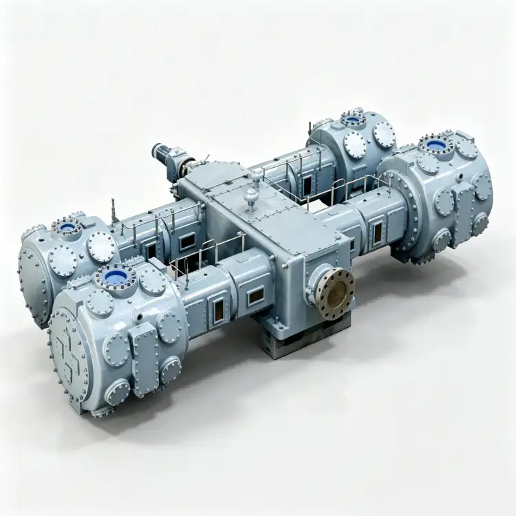
Pressure terms used in the ratio
- absolute suction pressure
- Local atmospheric pressure plus suction gauge pressure, adjusted to the actual inlet measurement point.
- absolute discharge pressure
- Local atmospheric pressure plus discharge gauge pressure at the defined outlet location.
- compression ratio
- P2_abs divided by P1_abs for the whole compressor or an individual stage.
- gauge pressure
- Pressure referenced to local atmosphere; useful operationally but not directly suitable for ratio calculations.
- stage ratio
- Absolute outlet pressure divided by absolute inlet pressure for one compression stage.
- pressure loss
- Drop through filters, coolers, valves, separators and piping that changes the pressure actually seen by each stage.
1. Identify the two pressure locations first
The suction pressure should be the pressure at or very near the compressor inlet flange, not a remote generator outlet unless the loss between them is negligible and verified. The discharge pressure should be the pressure at the compressor outlet used for performance, not automatically the pressure required at a distant process user. If the user needs a certain pressure after a long pipeline, calculate the intervening loss separately and add the required compressor discharge pressure transparently. This makes the ratio traceable and helps distinguish compressor sizing from piping design.
2. Convert both pressures to absolute
If a suction gauge reads 4 barg, the absolute suction pressure is roughly that gauge value plus local atmospheric pressure; use the actual atmospheric basis appropriate to the calculation. The same applies to discharge. The mistake of dividing two gauge readings becomes severe when suction pressure is low because atmospheric pressure is a large fraction of the true denominator. Always write “bara” or another explicit absolute notation on the calculation sheet. If the project uses kPa, MPa or psi, the ratio is dimensionless as long as both pressures are in the same unit and on the same absolute basis.
3. Calculate normal and limiting overall ratios
Calculate r for the normal operating point, then repeat it for the lowest credible suction pressure and highest required discharge pressure. The limiting ratio may occur during generator pressure decay, a dirty suction filter, hot low-density operation or a high process setpoint. Also check the highest suction pressure because a lower ratio can coincide with greater mass flow and driver load. Compression ratio is only one lens on the envelope; use it together with flow and inlet density. A table of several duty cases is often more informative than one headline ratio.
A useful next check is the site’s nitrogen compressor compression ratio material, especially when pressure, purity, and continuous-duty requirements interact. The cross-check here is tied to calculate nitrogen compressor compression ratio.

4. Estimate stage ratio only as a preliminary check
For n stages with strong intercooling, an idealized equal stage ratio can be estimated as r_stage = r_total^(1/n). This is useful for checking whether a proposed pressure split is wildly unbalanced. It is not a final design rule. Real stage pressures include pressure drop through intercoolers and separators, discrete cylinder sizes, valve losses and mechanical limits. The compressor supplier may intentionally use unequal ratios. Ask for the expected interstage pressures and temperatures so you can see how the actual design handles the overall duty.
5. Use ratio to interpret temperature and capacity changes
When suction pressure falls while discharge remains fixed, the ratio rises. The stage may run hotter and volumetric efficiency can change, reducing capacity. When suction pressure rises, ratio falls but inlet density rises, so mass throughput and power may increase. These effects explain why “lower compression ratio” does not automatically mean every load on the machine is lower. During troubleshooting, a sudden change in interstage ratio can indicate valve leakage, a restriction, cooler problem or change in downstream demand. Compare with the established baseline before opening the machine.

6. Document ratio in the operating envelope
Include normal and limiting ratios on the compressor data sheet along with the suction and discharge pressures that produced them. During commissioning, record actual pressures and calculate the observed ratio at representative loads. If performance differs from the guarantee, first confirm that the pressure locations and units match the contract basis. A compressor tested at a different suction pressure is operating at a different ratio even if the discharge setpoint is the same. Keeping the ratio calculation visible makes later capacity and temperature discussions much clearer.
Compression-ratio worksheet
| Item | Engineering question | Verification or decision signal |
|---|---|---|
| Pressure locations | Are P1 and P2 measured at the compressor boundaries used for the guarantee? | The ratio reflects the machine rather than unknown piping losses. |
| Pressure basis | Are both values absolute and in consistent units? | The calculation is dimensionally correct. |
| Operating envelope | Are low suction and high discharge cases evaluated? | The limiting ratio is visible before selection. |
| Stage check | Are interstage pressures compared with an ideal equal-ratio screen? | Unexpected pressure splits can be questioned and later trended. |
| Record the final basis in the RFQ, commissioning file, or maintenance record so another engineer can reproduce the decision. | ||
Project verification worksheet
During engineering review, challenge the assumption behind “convert gauge to absolute” by tracing the physical path associated with absolute suction pressure and compression ratio. Follow the gas, heat, force, control signal, or leakage route from source to destination and identify every component that can alter the result. Then complete “Locate suction and discharge pressure points on the P&ID or package drawing.” at the point where the decision is actually made, not at the most convenient gauge. Record any pressure drop, temperature difference, control delay, or inspection finding that explains the behavior. This path-based check prevents local measurements from being interpreted without system context.
To keep the engineering and purchasing teams on the same basis, relate this requirement to the site’s N2 compressor information. The cross-check here is tied to calculate nitrogen compressor compression ratio.
Make the verification for “Convert gauge readings to absolute pressure.” usable during a future fault investigation. Capture absolute discharge pressure, gauge pressure, compressor state, demand state, and observation time in one record. Link that record to the design intent “calculate overall ratio” and note which drawing, manual, process specification, or calibrated tool established acceptance. If the reading is normal, it becomes a reference. If it is abnormal, document corrective action and retest at the same condition. Consistent records reduce the temptation to compensate for an unexplained problem by increasing pressure, speed, temperature limits, or unrelated settings.
Verify “allocate stage ratios” at the boundary where its consequence appears. Observe compression ratio at its source and stage ratio at the receiving side, then complete “Calculate P2_abs/P1_abs for normal operation.” while relevant flow and pressure are stable. Record enough context to distinguish normal process variation from equipment deterioration. When exact acceptance limits depend on the selected model, use current manufacturer documentation or the approved project specification. Do not transfer a value from another compressor merely because the service sounds similar. A boundary-to-boundary record makes later troubleshooting much faster.
Close the loop on “Repeat the calculation for minimum suction and maximum required discharge.” by documenting cause, response, and acceptance. Start with “include piping losses”, identify the expected behavior of gauge pressure, and choose a second observation involving pressure loss that can confirm the same conclusion independently. Perform the check without bypassing protective devices or exceeding the approved operating range. If the two signals disagree, investigate instrument accuracy, valve state, pressure loss, contamination, leakage, or control logic before deciding which component needs work. Independent confirmation is valuable when shutdown or replacement would be expensive.
Turn the review item “check inlet variation” into a recorded acceptance step. Identify where stage ratio is observed, the operating state at that moment, and what upstream or downstream condition could change absolute suction pressure. Record the instrument, drawing, datasheet, or physical inspection used to establish the basis. Then perform the action “Use r_total^(1/n) only as an initial stage-ratio reasonableness check.” under a repeatable condition. If the result conflicts with expected behavior, hold the next design or maintenance decision until the discrepancy is explained. This gives another engineer enough context to reproduce the check without relying on memory or an undocumented assumption.
Use pressure loss as a field checkpoint tied to “Record interstage pressures during commissioning for future diagnostics.”. Write down the measurement or inspection location, gas state, compressor load, relevant valve positions, and the document that defines acceptance. Cross-check absolute discharge pressure at the same time so a local symptom is not mistaken for a whole-system problem. The concept “interpret the result” is complete only when the observation leads to a clear decision: accept, correct, or escalate for supplier review. Repeat the check after any correction and keep the before-and-after values with the commissioning or maintenance record.
For an application-specific cross-check, use the site’s medium capacity nitrogen compressor page alongside the measured duty data discussed above. The cross-check here is tied to calculate nitrogen compressor compression ratio.
Safety and verification boundary
Compression ratio is a calculation aid, not an allowable-pressure statement. Never use it to infer that a cylinder, cooler, vessel or pipe is safe at a given pressure. Maximum allowable pressure, relief settings and shutdown limits come from approved equipment and project documents. When reading or installing pressure instruments on nitrogen service, follow the site procedure for isolation and depressurization.
Calculation steps
- Locate suction and discharge pressure points on the P&ID or package drawing.
- Convert gauge readings to absolute pressure.
- Calculate P2_abs/P1_abs for normal operation.
- Repeat the calculation for minimum suction and maximum required discharge.
- Use r_total^(1/n) only as an initial stage-ratio reasonableness check.
- Record interstage pressures during commissioning for future diagnostics.
Compression-ratio questions
Can I divide discharge barg by suction barg?
No. Compression ratio must use absolute pressures. Gauge pressure has atmospheric pressure removed and therefore gives the wrong ratio.
What compression ratio requires two stages?
There is no universal cutoff. Stage count depends on gas temperature, cylinder and valve design, speed, cooling, pressure losses and manufacturer limits. Use ratio as a screening input.
Why does the ratio change if only suction pressure changes?
Because the denominator is changing. A lower absolute suction pressure increases P2/P1 for the same discharge pressure, which can raise temperature and reduce capacity.
Compression-ratio rule
Calculate nitrogen compressor compression ratio with absolute pressures at defined compressor boundaries. Evaluate several operating cases rather than one nominal ratio, and use the result to discuss staging, temperature and capacity with the supplier. The simple ratio becomes useful when its pressure locations and operating context are explicit.

























