
Build the duty point before you choose the compressor
Pressure, flow and duty cycle must describe the same operating case or the selection will be internally inconsistent.
An N2 compressor should be selected from a defined operating envelope, not from a single flow number copied from a process summary. Start by identifying where the nitrogen comes from, where pressure is required, how the flow changes over time, and how long each operating state lasts. A compressor fed from a PSA generator, a membrane unit, a liquid-nitrogen vaporizer, or a low-pressure plant header can see very different suction conditions even when the downstream user asks for the same discharge pressure. The selection therefore has to connect the source and the user. The most useful design sheet has separate rows for minimum, normal, and maximum suction pressure; normal and peak nitrogen demand; required pressure at the point of use; expected inlet temperature; and the duration of peak events. It should also state whether flow is normalized or actual and whether pressure is gauge or absolute. Once those basics are explicit, the compressor manufacturer can evaluate cylinder sizing, staging, speed, cooling and controls against a real duty rather than a vague request for “high-pressure nitrogen.”
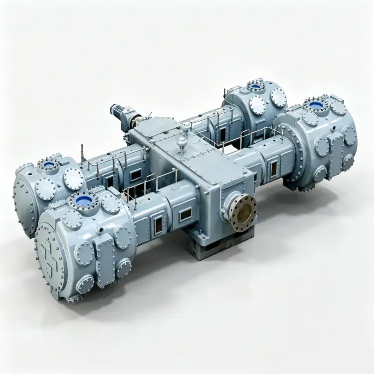
The six numbers that define the duty
- suction pressure
- Use the pressure expected at the compressor inlet flange, including losses between the nitrogen source and the machine.
- tekanan pelepasan
- Define the pressure required at the user and then add only the verified downstream pressure losses between compressor and process.
- normal flow
- State the continuous or most frequent nitrogen demand on a declared reference basis such as Nm3/h at stated normal conditions.
- peak flow
- Describe both the magnitude and duration of the peak so storage and compressor capacity can be evaluated separately.
- duty cycle
- Record how long the compressor loads, unloads, idles, stops or operates near maximum load during a representative production cycle.
- turndown
- Identify the lowest stable throughput the package must accommodate without excessive cycling, venting or recycle.
1. Put suction and discharge pressure on the same basis
Pressure errors are one of the fastest ways to mis-size a nitrogen compressor. Use absolute pressure for compression ratio and thermodynamic work, while plant instruments may continue to display gauge pressure for operations. More importantly, define the measurement location. A generator outlet transmitter may read acceptably while a dirty filter, undersized suction line, regulator or partially closed valve causes a lower pressure at the compressor flange. The compressor should be checked against the lowest credible suction pressure because that condition reduces inlet gas density and usually increases the pressure ratio needed to reach the same discharge target. For the outlet side, work backward from the process requirement. Include verified losses through aftercoolers, receivers, filters, dryers, control valves and distribution piping, but do not add a large generic pressure allowance simply because the line loss has not been calculated.
2. Separate normal flow from short peak demand
A plant often needs two different answers: how much nitrogen is consumed over an hour and how much is needed for a short event. The normal flow determines sustained compressor loading and much of the energy use. A brief peak, such as a purge, filling step or simultaneous valve operation, may be more economically supplied from a receiver if the total gas inventory is modest. Build a time-based demand profile rather than selecting a compressor equal to the largest instantaneous number. For each event, record flow, duration and the minimum acceptable process pressure. Then compare the gas deficit during the peak with available receiver inventory and compressor contribution. This distinction prevents a unit from being oversized for an event that lasts only minutes, while also avoiding the opposite mistake of choosing a machine that can meet average consumption but allows the header pressure to collapse during production peaks.
For a related equipment benchmark, review the site’s nitrogen compressor sizing options while checking the operating assumptions in this section. The cross-check here is tied to select n2 compressor pressure flow rate duty.
3. Treat duty cycle as a thermal and mechanical requirement
“Continuous duty” is more than a marketing label. A compressor that operates close to rated load for long periods must reject heat continuously, keep valve and packing temperatures within the approved envelope, maintain lubrication where lubrication is used, and provide service access without creating unacceptable production risk. Intermittent operation creates a different set of issues: repeated starts, frequent load-unload transitions and large pressure swings can become the dominant stress. Document starts per production cycle, loaded hours, unloaded hours, expected standby time and the duration of maximum-pressure operation. If the machine will run in a hot compressor room or at high site elevation, include those conditions because cooling capacity and motor margin can change. Selection should match the actual operating pattern rather than assuming that a compressor suited to one hour at a test point will be equally comfortable operating there around the clock.

4. Check what happens when the nitrogen source moves
On-site generation systems rarely produce a perfectly fixed suction condition. PSA and membrane systems can change available flow with purity setpoint, feed-air condition and control state. A product receiver can smooth some of that variation, but the booster still needs a defined minimum inlet pressure and a control response when the upstream supply falls. For a bulk or vaporized nitrogen source, pressure may vary with storage and regulation strategy instead. Build the compressor envelope around the source that will actually be installed. Ask what the booster does when suction pressure declines: does capacity fall, does the controller unload, does a low-suction permissive stop the machine, or does recycle protect a minimum flow? This is especially important when a high-pressure user can consume receiver inventory faster than the nitrogen generator can replenish it.
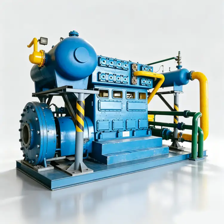
5. Match control strategy and receiver volume to demand behavior
Compressor capacity and receiver capacity should be designed together. A large receiver can absorb short peaks, reduce rapid cycling and give the upstream generator time to recover, but it does not solve a sustained capacity deficit. Likewise, a variable-speed drive can follow changing demand only within the speed range approved for the compressor, motor, lubrication and cooling arrangement. Other packages may use load-unload control, bypass or recycle, multiple machines in sequence, or a combination of methods. Plot expected demand against available compressor capacity at several suction pressures. Then decide what pressure band the receiver will operate within and how the controller will respond as the header approaches each setpoint. The objective is not simply a stable discharge gauge; it is a control system that keeps the compressor inside a healthy operating region while the user receives the required nitrogen.
6. Require a supplier performance point for the complete envelope
After the plant duty is defined, ask the supplier to return performance for the actual nitrogen condition rather than a generic air curve or an unrelated model. The response should identify capacity, suction condition, discharge pressure, driver requirement, staging, cooling utility and any limits that become important at the edge of the requested range. Review the low-suction/high-discharge case as carefully as the normal case because it often produces the highest compression ratio. Also review minimum demand so the control method is credible. If future expansion is expected, state the future case separately instead of silently embedding it in every present-day value. That makes the cost of expansion visible and helps avoid buying an oversized machine that spends its first years cycling. During commissioning, record the same variables used in the selection so the installed system can be compared with the approved duty point.
Use the site’s Kompresor N2 resource as a second check when translating this requirement into a compressor specification. The cross-check here is tied to select n2 compressor pressure flow rate duty.
Selection sanity check
| Item | Engineering question | Verification or decision signal |
|---|---|---|
| Pressure basis | Are suction and discharge pressures tied to named flanges and identified as gauge or absolute? | A reviewer can reproduce the compression ratio without guessing the pressure reference. |
| Flow profile | Are normal flow, peak flow and peak duration separated? | Storage and compressor capacity can be evaluated independently. |
| Duty cycle | Are loaded hours, starts and intermittent events described? | Cooling, controls and maintenance strategy match the real operating pattern. |
| Source variability | Is the lowest credible suction condition included? | The compressor remains within its envelope when the upstream nitrogen source weakens. |
| Record the final basis in the RFQ, commissioning file, or maintenance record so another engineer can reproduce the decision. | ||
Project verification worksheet
Turn the review item “build the duty point” into a recorded acceptance step. Identify where suction pressure is observed, the operating state at that moment, and what upstream or downstream condition could change normal flow. Record the instrument, drawing, datasheet, or physical inspection used to establish the basis. Then perform the action “Write minimum, normal and maximum suction pressure at the compressor inlet flange.” under a repeatable condition. If the result conflicts with expected behavior, hold the next design or maintenance decision until the discrepancy is explained. This gives another engineer enough context to reproduce the check without relying on memory or an undocumented assumption.
Use discharge pressure as a field checkpoint tied to “State the required process pressure and calculate downstream pressure losses separately.”. Write down the measurement or inspection location, gas state, compressor load, relevant valve positions, and the document that defines acceptance. Cross-check peak flow at the same time so a local symptom is not mistaken for a whole-system problem. The concept “separate normal and peak demand” is complete only when the observation leads to a clear decision: accept, correct, or escalate for supplier review. Repeat the check after any correction and keep the before-and-after values with the commissioning or maintenance record.
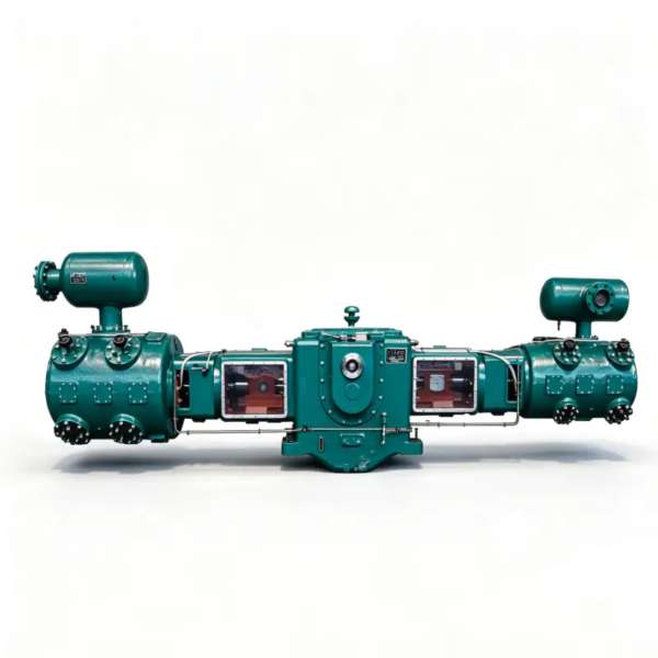
Verify “define pressure at the user” by creating one controlled condition in which normal flow and duty cycle can be interpreted together. Stabilize the system, note pressure, temperature, flow, or machine state as relevant, and use calibrated instruments or direct inspection at named locations. Carry out “List normal flow, peak flow and peak duration on a declared reference basis.” and record both expected and observed response. If a model-specific limit is required, obtain it from the selected compressor, vessel, piping, generator, or process documentation rather than inserting a generic value. The record should show why the final decision is technically defensible.
Before freezing the equipment choice, compare this duty with the site’s industrial N2 compressor range and confirm that the same pressure basis is being used. The cross-check here is tied to select n2 compressor pressure flow rate duty.
Safety and verification boundary
Nitrogen can displace oxygen, and compressed gas stores significant energy. Locate vents, relief outlets and purge discharges so they do not create an oxygen-deficient area. Before opening any part of the compressor or connected piping, isolate the energy source, depressurize the trapped volume and follow the site lockout and permit procedure. Relief devices, pressure vessels, electrical equipment and hazardous-area hardware must be selected to the codes and approved documents that apply to the project.
RFQ checklist before requesting a model
- Write minimum, normal and maximum suction pressure at the compressor inlet flange.
- State the required process pressure and calculate downstream pressure losses separately.
- List normal flow, peak flow and peak duration on a declared reference basis.
- Describe the loaded, unloaded, stopped and standby portions of the duty cycle.
- Define receiver operating pressure band and the compressor control philosophy.
- Ask the supplier to confirm performance at both the normal case and the limiting case.
Selection questions worth resolving early
Should I size the compressor for the highest instantaneous flow?
Not automatically. If the highest flow is brief, a receiver may supply part of the event while the compressor is sized closer to sustained demand. Calculate the gas inventory required during the peak and confirm that receiver pressure remains above the process minimum.
Which suction pressure should be used for sizing?
Use the lowest credible pressure at the compressor suction flange for the limiting capacity check, then also evaluate normal and maximum inlet pressure. The machine and controls must tolerate the full range.
How much spare capacity should I add?
Add only a justified allowance tied to known uncertainty, leakage, degradation or future expansion. Keep future demand as a separate case so the team can see whether the additional capacity is truly needed now.
Selection rule to keep
A defensible N2 compressor selection is a matched set of pressure, flow and time-based requirements. Define the source, the user and the control behavior between them. When the RFQ states suction pressure range, discharge requirement, normal and peak flow, peak duration, duty cycle and expected turndown, the supplier can size the compressor for the real service and the commissioning team has a clear basis for acceptance.

























